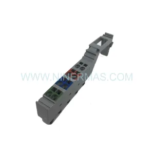
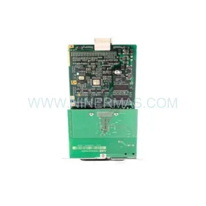
Original Industrial Spare Part
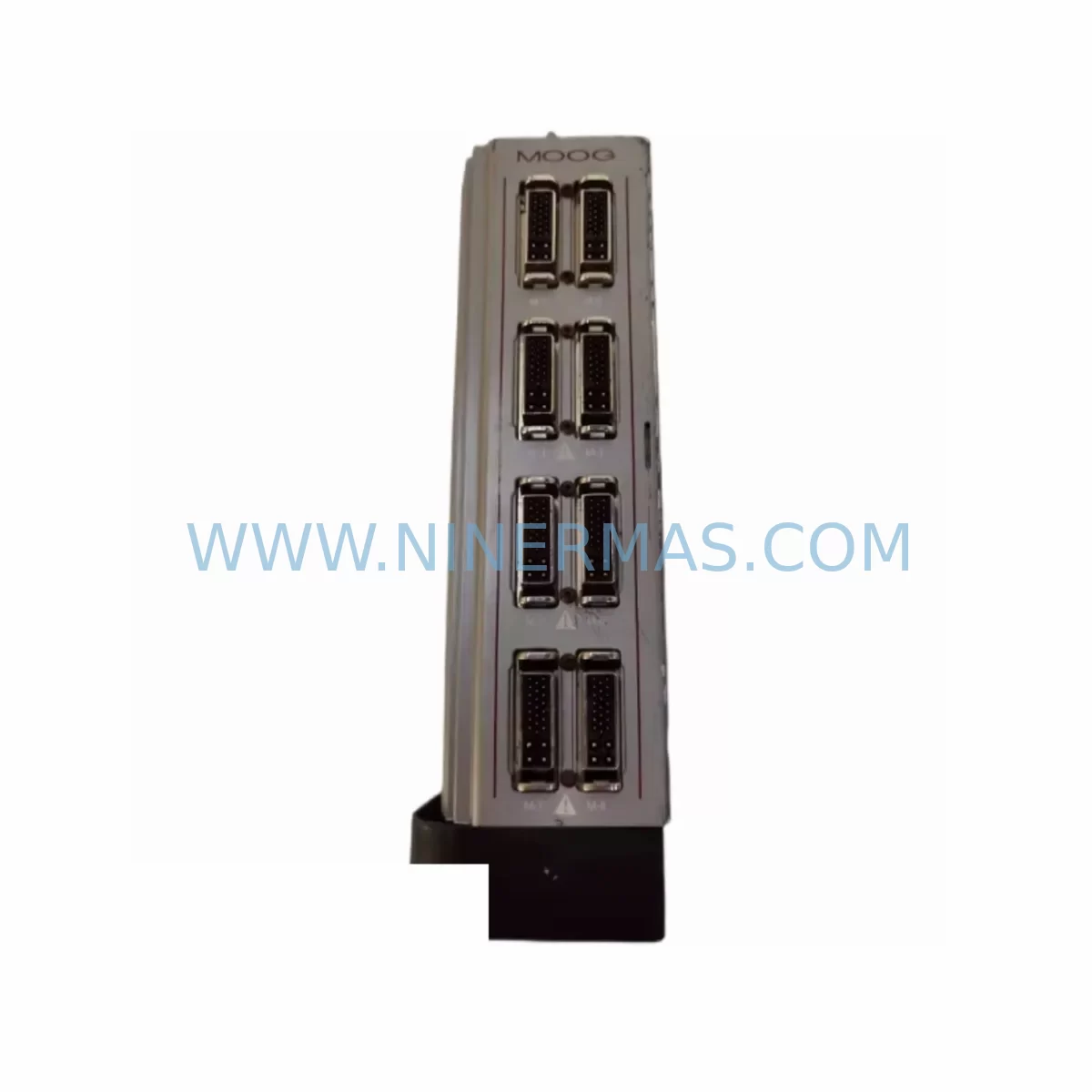
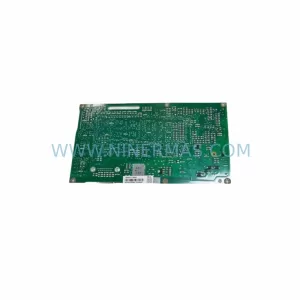
MOOG 110-000-028-03 Retrofit-Compatible Drive for Legacy Systems
Verify the part, confirm the platform family, and move straight into quotation with the right commercial details.
RFQ Ready
- SKU110-000-028-03 BX-300A
- CategoryPLC & Industrial Automation Modules
- BrandMOOG
- SupportAvailability, lead time, condition, and shipping coordination
How Buyers Usually Use This Page
- Confirm the exact part number and platform family before sending the quote request.
- Use direct email when quantity, condition, and destination are already defined internally.
- Switch to the broader brand or category archive when you need alternates nearby.
Series Navigation
Move through the most common platform families behind this part.
Product RFQ
Send this part directly for quotation.
Include quantity, required condition, destination country, and target delivery timing. Current reference: MOOG 110-000-028-03 Retrofit-Compatible Drive for Legacy Systems with SKU 110-000-028-03 BX-300A.
MOOG 110-000-028-03 Retrofit-Compatible Drive for Legacy Systems: Seamless BX Series Upgrade
The MOOG 110-000-028-03 is a retrofit-compatible servo drive engineered to replace and modernize legacy BX-300A servo amplifier installations across aging industrial automation platforms. As the BX-300A reaches end-of-life status and original spare parts become increasingly scarce, the 110-000-028-03 provides a verified, drop-in-compatible upgrade path that preserves existing wiring infrastructure, control cabinet layouts, and motion program logic. For maintenance engineers managing legacy MOOG BX series systems, this unit represents a critical bridge between discontinued hardware and continued production uptime.
Industrial facilities running MOOG BX series servo systems often face a common challenge: the original BX-300A servo amplifier is no longer manufactured, and sourcing genuine replacement units through standard distribution channels has become unreliable. The 110-000-028-03 addresses this directly by maintaining electrical compatibility with the BX-300A’s power input specifications, feedback interface pinout, and command signal architecture. Engineers can install this unit into the existing control cabinet without redesigning the backplane wiring or modifying the servo motor feedback cable harness.
Before beginning the retrofit, engineers should verify the power supply capacity available in the existing cabinet. The BX-300A typically operates on a 24 VDC logic supply alongside a higher-voltage DC bus, and the 110-000-028-03 shares this power architecture. If the existing MOOG T161-907A-24-H1 power supply module is still serviceable, it can remain in place during the upgrade. However, if the power supply has also reached end-of-life, it is advisable to replace it concurrently to avoid a secondary unplanned outage. Terminal wiring should be documented with photographs before disconnection, and each conductor should be labeled according to the original MOOG wiring diagram to ensure accurate reconnection.
The backplane interface and module addressing must also be confirmed prior to installation. In multi-axis BX series configurations, each servo drive occupies a defined node address on the motion network. The 110-000-028-03 supports the same node addressing scheme as the BX-300A, which means the axis address set on the original unit can be replicated on the replacement without modifying the motion controller configuration. If the system uses a MOOG D136-001-007 servo controller or a compatible D136-001-009 variant as the master controller, the axis mapping in the controller program does not require revision.
Communication protocol continuity is a key concern during any servo drive replacement. The BX series platform typically communicates via a proprietary MOOG serial link or an analog ±10 V command interface, depending on the system generation. The 110-000-028-03 supports both interface modes, allowing engineers to maintain the existing communication link without installing a protocol converter or modifying the HMI screen logic. If the facility uses a MOOG G122-829 communication gateway module to bridge the BX series network to a higher-level SCADA or DCS system, this gateway remains fully compatible with the 110-000-028-03.
I/O expansion and signal isolation should also be reviewed during the retrofit planning phase. In systems where the BX-300A interfaces with external I/O modules such as the MOOG T161-207 digital I/O expansion card, the signal wiring and logic assignments should be verified against the replacement unit’s I/O terminal map. Signal isolators installed between the servo drive and field sensors should be retained, as they protect the new drive from electrical noise generated by legacy wiring runs. The BX-310 servo amplifier, used in adjacent axes within the same control cabinet, does not require replacement if it remains functional, but its firmware version should be checked for compatibility with the updated axis configuration.
HMI screen updates are typically minimal when replacing the BX-300A with the 110-000-028-03, provided the axis tag names and drive status registers remain consistent. Engineers should confirm that any fault code displays on the operator panel correctly map to the new drive’s diagnostic register layout. In most BX series installations, the HMI communicates with the motion controller rather than directly with the servo drive, which further reduces the scope of HMI modifications required.
Installation space within the control cabinet should be measured before ordering the replacement unit. The 110-000-028-03 maintains a form factor consistent with the BX-300A, but thermal clearance requirements should be re-evaluated if the cabinet has been modified since original installation. Adequate airflow around the drive is essential for long-term reliability, particularly in high-duty-cycle applications such as press automation, winding machinery, and precision positioning systems.
All units supplied by NINERMAS undergo pre-shipment functional testing to verify drive enable response, feedback signal processing, and fault detection behavior. Each 110-000-028-03 is shipped with a 12-month warranty covering manufacturing defects and component failures under normal operating conditions. Inventory is maintained in-house to support urgent replacement requirements, with same-day dispatch available for confirmed orders received before the daily shipping cutoff.
Upgrade Compatibility Table
| Parameter | BX-300A (Original) | 110-000-028-03 (Replacement) |
|---|---|---|
| Power Input | 24 VDC Logic / DC Bus | Compatible — same power architecture |
| Feedback Interface | Resolver / Encoder (BX standard) | Compatible — same pinout retained |
| Command Interface | ±10 V Analog / Serial Link | Both modes supported |
| Node Addressing | Hardware DIP switch | Same addressing scheme — no controller change |
| Backplane / Rack | BX Series rack mount | Same form factor — direct rack installation |
| Communication Protocol | MOOG proprietary serial / analog | Fully compatible — no gateway required |
| Installation Space | Standard BX drive slot | Equivalent footprint — verify thermal clearance |
| Commissioning | MOOG BX commissioning tool | Compatible with existing commissioning software |
| Replacement Status | Discontinued / End-of-Life | In-stock retrofit replacement |
| Warranty | N/A (EOL) | 12-Month Warranty from NINERMAS |
Retrofit Planning for Existing Automation Systems
A successful BX-300A to 110-000-028-03 retrofit begins with a structured pre-outage audit. The maintenance team should collect the existing wiring diagrams, axis configuration files, and motion program backups before scheduling the replacement window. If the system uses a MOOG BX-CAN communication cable to link multiple drive axes, the cable routing and connector condition should be inspected at the same time, as degraded connectors are a common source of intermittent faults in aging BX series installations.
The servo motor connected to the BX-300A should also be inspected during the retrofit. Insulation resistance testing of the motor windings and feedback cable continuity checks will confirm whether the motor itself is contributing to any existing drive faults. In systems where the motor has been in service for more than ten years, it may be advisable to replace the feedback cable simultaneously with the drive, as cable insulation degradation can cause resolver signal errors that are difficult to distinguish from drive faults during initial commissioning.
For multi-axis systems, the replacement of a single BX-300A axis should be coordinated with the motion controller to ensure that the remaining axes, which may include BX-310 servo amplifiers or other BX series variants, continue to operate normally during the single-axis outage. The D136-001-007 or D136-001-009 controller should be placed in a safe hold state before the drive is removed, and the axis enable signal should be confirmed as de-energized before disconnecting any power terminals.
After installation of the 110-000-028-03, the commissioning sequence should follow the standard MOOG BX drive startup procedure: verify logic power, confirm feedback signal quality, enable the drive in torque mode to check motor response, then transition to velocity and position control modes. Any parameter adjustments required to match the original axis tuning should be documented and stored in the facility’s maintenance management system for future reference.
Downtime Control During System Migration
Minimizing unplanned downtime during a BX-300A replacement requires preparation that begins well before the maintenance window. The most effective approach is to pre-stage the 110-000-028-03 in the facility before the scheduled outage, verify its physical condition and firmware version, and prepare all required tools and documentation in advance. A pre-tested replacement unit eliminates the risk of discovering a shipping damage issue during the outage window.
The original motion program logic stored in the MOOG D136-001-007 or D136-001-009 controller does not require modification when replacing the BX-300A with the 110-000-028-03, provided the axis address and communication interface settings are replicated correctly. This means the program backup taken before the outage can be reloaded without modification after the new drive is installed, significantly reducing the time required to restore production.
Field control continuity during the migration can be maintained by ensuring that all adjacent axes remain in a safe, controlled hold state rather than an uncontrolled stop. If the production line includes safety interlocks that trigger an emergency stop when any axis faults, the maintenance team should coordinate with the production supervisor to implement a controlled line stop before beginning the drive replacement. This prevents uncontrolled material movement and protects both personnel and in-process workpieces.
Post-installation verification should include a full axis cycle test at reduced speed before returning the system to production speed. This confirms that the feedback signal, command response, and fault detection functions are all operating correctly before the system is exposed to full production loads. The total planned outage window for a single-axis BX-300A replacement with the 110-000-028-03 is typically two to four hours for an experienced maintenance team with all materials pre-staged.
Retrofit Support FAQ
Q: Is the MOOG 110-000-028-03 a direct replacement for the BX-300A?
A: Yes. The 110-000-028-03 is designed as a retrofit-compatible replacement for the BX-300A, maintaining compatibility with the original power input, feedback interface, command signal, and node addressing scheme. No modifications to the existing wiring or motion controller program are required in standard BX series configurations.
Q: Does NINERMAS test the 110-000-028-03 before shipment?
A: Yes. Every unit undergoes pre-shipment functional testing covering drive enable response, feedback signal processing, and fault detection behavior. A test report is available upon request. All units are covered by a 12-month warranty from the date of shipment.
Q: What wiring documentation should I prepare before starting the retrofit?
A: Collect the original MOOG BX series wiring diagram, photograph all terminal connections before disconnection, and label each conductor. Verify the axis node address set on the BX-300A so it can be replicated on the 110-000-028-03. Confirm the logic power supply voltage and DC bus voltage before energizing the replacement unit.
Q: How quickly can NINERMAS ship the 110-000-028-03 for an urgent replacement?
A: The 110-000-028-03 is maintained in in-house inventory to support urgent requirements. Same-day dispatch is available for confirmed orders received before the daily shipping cutoff. Contact sale@ninermas.com or call +0086 187 5021 5667 to confirm current stock availability and lead time.
| Product Series | Legacy |
|---|
Catalog Continuation
More MOOG modules in the catalog.
Use the brand lane to compare nearby part numbers, platform-adjacent modules, and other inquiry-ready listings before sending your final RFQ.
SKU: IMI220-422A001
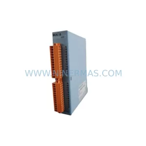
MOOG IMI220-422A001 Retrofit-Compatible Machine Controller
SKU: IMI220-481A001
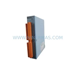
MOOG IMI220-481A001 Safety-Reliable Servo for Critical Control
Catalog Continuation
Alternative parts within PLC & Industrial Automation Modules.
Stay inside the same system family when you need substitutes, adjacent modules, or a broader shortlist for procurement review.
SKU: 6FC5357-0BB12-0AE0
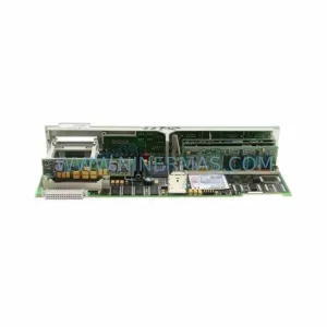
Siemens 6FC5357-0BB12-0AE0 Service-Ready Industrial Spare Part
SKU: 3BSE011790R1(PXHK401)
ABB 3BSE011790R1 PXHK401 Retrofit-Ready Communication Module