Original Industrial Spare Part
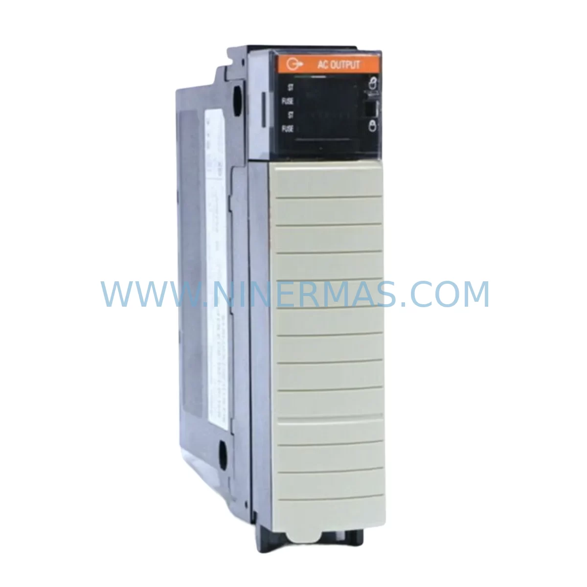
Allen-Bradley 1756-OA16I Retrofit-Compatible AC Output Module
Verify the part, confirm the platform family, and move straight into quotation with the right commercial details.
RFQ Ready
- SKU1756-OA16I
- CategoryPLC & Industrial Automation Modules
- BrandAllen-Bradley
- SupportAvailability, lead time, condition, and shipping coordination
How Buyers Usually Use This Page
- Confirm the exact part number and platform family before sending the quote request.
- Use direct email when quantity, condition, and destination are already defined internally.
- Switch to the broader brand or category archive when you need alternates nearby.
Series Navigation
Move through the most common platform families behind this part.
Product RFQ
Send this part directly for quotation.
Include quantity, required condition, destination country, and target delivery timing. Current reference: Allen-Bradley 1756-OA16I Retrofit-Compatible AC Output Module with SKU 1756-OA16I.
Allen-Bradley 1756-OA16I Retrofit-Compatible AC Output Module: Legacy System Compatibility & Smooth Upgrade
The Allen-Bradley 1756-OA16I is a 16-point, individually isolated AC output module designed for the ControlLogix platform. As legacy automation systems age and original spare parts become increasingly difficult to source, the 1756-OA16I remains one of the most sought-after retrofit components for facilities running older 1756-series control architectures. Whether you are replacing a failed module in an existing control cabinet, migrating from an aging PLC-5 or SLC 500 platform, or expanding I/O capacity within a ControlLogix chassis, the 1756-OA16I delivers the output isolation and load flexibility that industrial environments demand.
Each output point on the 1756-OA16I is individually isolated, making it particularly well-suited for applications where load circuits must remain electrically independent — a critical requirement in legacy panel retrofits where mixed-voltage field devices are common. The module supports 10–265V AC loads and is compatible with the standard 1756 backplane, allowing direct installation into any ControlLogix chassis without additional adapters or wiring harnesses.
When planning a retrofit around the 1756-OA16I, engineers must verify several key parameters before committing to installation. Power supply capacity is the first checkpoint: the 1756-PA75 or 1756-PB75 power supplies commonly found in legacy ControlLogix racks must be assessed to confirm they can support the additional backplane current draw introduced by the replacement module. Terminal block wiring should be reviewed against the original I/O wiring diagrams — the 1756-OA16I uses a 36-pin RTB (Removable Terminal Block), and any deviation from the original wiring map must be corrected before energizing the system.
Backplane slot addressing is another area requiring careful attention. In a ControlLogix system, each module’s slot number determines its logical address within the controller tag database. When replacing a failed 1756-OA16I, the replacement module must be installed in the same chassis slot to preserve existing ladder logic and tag references. If the slot assignment has changed — for example, due to chassis reconfiguration or the addition of a 1756-EN2T EtherNet/IP communication module — the program logic in Studio 5000 Logix Designer must be updated accordingly before going live.
Program compatibility is a frequent concern during legacy system upgrades. Projects originally developed in RSLogix 5000 can be opened and validated in Studio 5000, but output module configurations — including RPI (Requested Packet Interval) settings, fault states, and output data mapping — must be reviewed to ensure they align with the replacement module’s firmware version. In systems where a 1756-L63 or 1756-L71 controller is in service, the I/O tree should be refreshed after module replacement to confirm the 1756-OA16I is recognized and communicating correctly on the backplane.
HMI screen updates are often overlooked during module swaps. If the facility operates a PanelView Plus 7 or a legacy PanelView 1000 terminal linked to output status tags derived from the 1756-OA16I, any tag renaming or address changes introduced during the retrofit must be propagated to the HMI project to prevent alarm suppression or incorrect status displays on the operator interface.
Communication link integrity should be verified after installation. In distributed control architectures where the ControlLogix rack communicates over a 1756-ENBT or 1756-EN2TR EtherNet/IP bridge module, the network topology and IP addressing scheme must remain intact throughout the module replacement process. Disruption to the backplane communication path — even briefly — can trigger controller faults that require a full program download to clear.
Installation space confirmation is straightforward for the 1756-OA16I, as it occupies a single slot in any standard 1756 chassis, including the 1756-A4, 1756-A7, 1756-A10, and 1756-A17 chassis variants. However, in densely populated control cabinets, thermal management must be considered: the module’s heat dissipation characteristics should be factored into the overall cabinet thermal load calculation, particularly in high-ambient-temperature environments.
Field commissioning of the 1756-OA16I follows a structured sequence. After physical installation and RTB wiring, the module should be powered up with the controller in Program mode. A forced output test — conducted point by point using the controller’s I/O forcing function — confirms that each of the 16 output channels is wiring correctly to its corresponding field device. Only after all 16 points have been verified should the controller be switched to Run mode and normal production resumed.
Upgrade Compatibility Table
| Parameter | Details |
|---|---|
| Module SKU | 1756-OA16I |
| Platform | Allen-Bradley ControlLogix (1756 Series) |
| Output Points | 16 (Individually Isolated) |
| Voltage Range | 10–265V AC |
| Backplane Interface | Standard 1756 Backplane (single slot) |
| Compatible Chassis | 1756-A4, 1756-A7, 1756-A10, 1756-A17 |
| Terminal Block | 36-pin RTB (Removable Terminal Block) |
| Communication Compatibility | EtherNet/IP, ControlNet, DeviceNet (via bridge modules) |
| Replacement / Retrofit Path | Direct replacement for failed or end-of-life 1756-OA16I units |
| Programming Software | RSLogix 5000 / Studio 5000 Logix Designer |
| Installation Requirement | Same chassis slot as original module recommended |
| Commissioning Method | I/O forced output test, point-by-point verification |
| Warranty | 12 Months |
Retrofit Planning for Existing Automation Systems
A successful retrofit centered on the 1756-OA16I requires a coordinated approach across hardware, software, and field wiring. In a typical legacy ControlLogix system, the 1756-OA16I coexists with a range of complementary modules that must all be accounted for during the upgrade plan. The 1756-IA16 and 1756-IA32 AC input modules share the same backplane and RTB wiring conventions, so any changes to the output module’s slot assignment will ripple through the input module addressing as well.
Power distribution within the chassis is managed by the 1756-PA75 or 1756-PB75 power supply modules. Before adding or replacing a 1756-OA16I, the total backplane current budget must be recalculated to ensure the power supply is not operating near its rated capacity. In systems where the existing power supply is already heavily loaded — for example, in a 1756-A17 chassis populated with multiple analog modules such as the 1756-IF16 and 1756-OF8 — a power supply upgrade may be necessary before the output module replacement can proceed safely.
Communication infrastructure is equally important. Many legacy ControlLogix systems rely on a 1756-ENBT or 1756-EN2T EtherNet/IP communication module to connect the controller to the plant network and to SCADA or DCS systems. During the retrofit, the communication module’s configuration should be backed up and its network parameters documented to prevent connectivity loss. In systems using ControlNet, the 1756-CNB or 1756-CNBR bridge modules must remain undisturbed throughout the output module replacement process.
For facilities migrating from older PLC-5 or SLC 500 platforms to ControlLogix, the 1756-OA16I is frequently specified as part of a broader I/O migration strategy. The 1756-DHRIO module enables legacy Data Highway Plus communication, allowing the new ControlLogix system to coexist with older PLC-5 controllers during a phased migration. Signal isolators and terminal block adapters are often required to bridge the wiring differences between the legacy I/O system and the new 1756-series modules.
Programming cable access is another practical consideration. The 1756-CP3 serial programming cable or a USB-to-serial adapter is typically required for initial controller configuration, while ongoing program management is handled via the EtherNet/IP network. Ensuring that the programming workstation has a licensed copy of Studio 5000 and the correct firmware revision for the 1756-L series controller is essential before beginning any program modifications associated with the 1756-OA16I replacement.
Downtime Control During System Migration
Minimizing production downtime during a 1756-OA16I replacement requires careful pre-planning and a disciplined execution sequence. The most effective approach is to prepare the replacement module, RTB wiring harness, and updated program file in advance — ideally during a scheduled maintenance window — so that the physical swap can be completed in the shortest possible time.
Before removing the failed module, the controller should be placed in Program mode and all output forcing should be disabled. The existing RTB should be disconnected from the module housing and labeled clearly to prevent wiring errors during reinstallation. The replacement 1756-OA16I should be inserted into the same chassis slot, the RTB reconnected, and the module allowed to complete its self-diagnostic cycle before the controller is returned to Run mode.
To protect the original program logic, a full project backup — including controller tags, I/O configuration, and HMI project files — should be completed before any hardware changes are made. This backup serves as the recovery baseline if the replacement module introduces unexpected compatibility issues. In systems where the controller firmware version does not match the replacement module’s supported firmware range, a firmware update may be required, which adds time to the migration window and should be factored into the downtime estimate.
Field control continuity can be maintained during brief outages by placing critical output devices in a safe, de-energized state before the module swap begins. For processes where even momentary output loss is unacceptable, a hot-standby ControlLogix configuration using a 1756-SRM (System Redundancy Module) can provide seamless failover during the replacement procedure, eliminating production impact entirely.
Retrofit Support FAQ
Q: Is the replacement 1756-OA16I a direct drop-in for the original module?
A: Yes. The 1756-OA16I is a direct slot-for-slot replacement within any standard 1756 ControlLogix chassis. The module uses the same 36-pin RTB wiring interface and the same backplane communication protocol as the original, so no hardware adapters or wiring modifications are required provided the replacement is installed in the same chassis slot.
Q: What commissioning steps are required after installing the replacement module?
A: After physical installation, place the controller in Program mode and verify that the 1756-OA16I appears correctly in the I/O tree within Studio 5000. Perform a point-by-point forced output test to confirm all 16 channels are wired correctly to their field devices. Once all points are verified, disable forcing and return the controller to Run mode. Document the commissioning results for maintenance records.
Q: How do I confirm wiring compatibility between the original and replacement module?
A: Compare the original I/O wiring diagram against the 1756-OA16I installation manual (Rockwell publication 1756-IN572). Pay particular attention to the RTB terminal assignments for each of the 16 output points and the common (neutral) terminals. If the original module was wired using a pre-wired cable assembly, verify that the cable assembly part number is compatible with the replacement module’s RTB connector.
Q: What warranty and supply assurance does NINERMAS provide for the 1756-OA16I?
A: NINERMAS provides a 12-month warranty on all 1756-OA16I units. Each module undergoes functional testing prior to shipment to verify backplane communication, output channel integrity, and self-diagnostic operation. We maintain inventory stock to support urgent retrofit and emergency replacement requirements. For lead time confirmation and volume pricing, contact sale@ninermas.com or call +0086 187 5021 5667.
| Product Series | ControlLogix |
|---|---|
| Country of Origin | US |
Catalog Continuation
More Allen-Bradley modules in the catalog.
Use the brand lane to compare nearby part numbers, platform-adjacent modules, and other inquiry-ready listings before sending your final RFQ.
Catalog Continuation
Alternative parts within PLC & Industrial Automation Modules.
Stay inside the same system family when you need substitutes, adjacent modules, or a broader shortlist for procurement review.
SKU: TRY/PRG/4-20MA/10-30DC
MOORE TRY/PRG/4-20MA/10-30DC Service-Ready Spare Part
SKU: 5085-404901-11 12INCH 2910-202413-12 404200XRMPD2H14 7-249717
TEL 5085-404901-11 Service-Ready Spare Part for Industrial Maintenance
SKU: DIP011 05-058-011
SIGMATEK DIP011 05-058-011 Service-Ready Spare Part