Original Industrial Spare Part
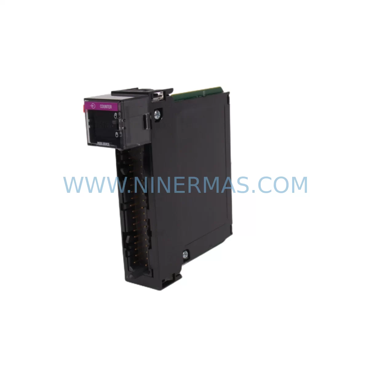
AB 1756-LSC8XIB8I Retrofit-Compatible Counter Input Module
Verify the part, confirm the platform family, and move straight into quotation with the right commercial details.
RFQ Ready
- SKU1756-LSC8XIB8I
- CategoryPLC & Industrial Automation Modules
- BrandAllen-Bradley
- SupportAvailability, lead time, condition, and shipping coordination
How Buyers Usually Use This Page
- Confirm the exact part number and platform family before sending the quote request.
- Use direct email when quantity, condition, and destination are already defined internally.
- Switch to the broader brand or category archive when you need alternates nearby.
Series Navigation
Move through the most common platform families behind this part.
Product RFQ
Send this part directly for quotation.
Include quantity, required condition, destination country, and target delivery timing. Current reference: AB 1756-LSC8XIB8I Retrofit-Compatible Counter Input Module with SKU 1756-LSC8XIB8I.
AB 1756-LSC8XIB8I Retrofit-Compatible Counter Input Module for Legacy System Upgrades
The Allen-Bradley 1756-LSC8XIB8I is a ruggedized, high-speed counter input module designed for the ControlLogix platform, engineered to withstand harsh industrial environments where vibration, temperature extremes, and electromagnetic interference are constant operational realities. As legacy automation systems age and OEM support for discontinued modules becomes increasingly difficult to secure, the 1756-LSC8XIB8I has emerged as a critical retrofit component for engineers tasked with modernizing existing control architectures without triggering full-system replacements.
For facilities running older SLC 500 or PLC-5 platforms, migrating counter input functionality to the ControlLogix backplane via the 1756-LSC8XIB8I represents a cost-effective path forward. The module slots directly into a 1756 chassis — including the 1756-A4, 1756-A7, 1756-A10, and 1756-A13 rack configurations — and communicates natively over the ControlLogix backplane without requiring additional gateway hardware. Engineers replacing legacy 1771-IJ or 1771-IK counter input modules from the PLC-5 era will find the 1756-LSC8XIB8I a functionally compatible successor, provided that terminal wiring, encoder signal types, and pulse frequency ranges are verified against the new module’s specifications prior to installation.
Before committing to a retrofit plan, the engineering team should confirm available power budget on the 1756-PA75 or 1756-PB75 power supply currently installed in the chassis. The 1756-LSC8XIB8I draws current from the backplane, and in densely populated racks — particularly those already hosting 1756-IB16, 1756-OB16E, or 1756-IF8 analog input modules — power headroom must be calculated carefully to avoid nuisance faults or unexpected shutdowns during commissioning. If the existing power supply is operating near capacity, upgrading to a higher-rated 1756-PA72 or adding a redundant supply should be factored into the project scope.
Upgrade Compatibility Table
| Parameter | Legacy Module (e.g. 1771-IJ) | 1756-LSC8XIB8I | Retrofit Notes |
|---|---|---|---|
| Platform | PLC-5 / 1771 Chassis | ControlLogix / 1756 Chassis | Chassis and backplane replacement required |
| Counter Channels | 4–8 (model dependent) | 8 isolated counter inputs | Channel mapping must be re-verified in Logix Designer |
| Input Voltage | 5V / 12V DC | 10–30V DC (IB8I spec) | Field wiring voltage levels must be confirmed |
| Terminal Wiring | 1771-style screw terminals | Removable RTB (1756-TBCH or equivalent) | New terminal block required; rewiring recommended |
| Backplane Interface | 1771 parallel backplane | ControlLogix serial backplane | Full backplane migration; no direct adapter available |
| Module Addressing | Rack/Group/Slot (PLC-5 style) | Slot-based, tag-addressed | Program logic must be converted to tag-based addressing |
| Communication Protocol | DH+ / Remote I/O | EtherNet/IP via 1756-EN2T or 1756-ENBT | Communication module upgrade required |
| Programming Software | RSLogix 5 | Studio 5000 Logix Designer | Program conversion and re-validation required |
| Installation Space | Single 1771 slot | Single 1756 slot | Confirm cabinet depth and rail clearance |
| Commissioning | Hardware configuration via DIP switch | Software configuration in Logix Designer | Online configuration; no physical switch setting required |
| Warranty | OEM support discontinued | 12-Month Warranty (NINERMAS) | Covered from date of shipment |
Retrofit Planning for Existing Automation Systems
A successful retrofit centered on the 1756-LSC8XIB8I begins well before the module arrives on-site. The first step is a thorough audit of the existing control cabinet: document every module currently occupying the 1771 or older 1756 chassis, including I/O modules, communication adapters, and specialty cards. In many legacy installations, the counter input module shares a rack with discrete I/O cards such as the 1756-IB32 or 1756-OB32, analog modules like the 1756-IF16, and communication bridges including the 1756-DHRIO for legacy DH+ network connectivity. Each of these components must be evaluated for compatibility with the new ControlLogix architecture before the cutover date is confirmed.
Terminal wiring is one of the most time-consuming aspects of any counter module retrofit. The 1756-LSC8XIB8I uses a removable terminal block — typically the 1756-TBCH or 1756-TBS6H — which must be ordered alongside the module if not already available in the facility’s spare parts inventory. Field cables connecting encoders, proximity sensors, or pulse-generating devices to the legacy module will need to be re-terminated to match the new RTB pinout. Engineers should prepare a detailed wiring diagram cross-referencing the old terminal assignments with the new module’s channel layout before any field work begins.
On the software side, the transition from RSLogix 5 or RSLogix 500 to Studio 5000 Logix Designer requires a structured program conversion effort. Counter accumulator values, preset registers, and output control bits that were previously addressed using file-based notation (e.g., C5:0.ACC) must be remapped to tag-based structures in the new Logix project. If the facility uses a PanelView or PanelView Plus HMI — such as the 2711P-T10C4D8 or 2711-T10C20 — the HMI screens referencing counter data tags will also require updating to reflect the new tag names and data types. This HMI rework is frequently underestimated in project timelines and should be allocated dedicated engineering hours.
For systems that rely on high-speed pulse counting for production throughput measurement or encoder position feedback, the signal integrity of the field wiring must be validated after re-termination. Shielded cable grounding, cable routing away from high-voltage conductors, and proper termination resistance at the module input are all factors that influence counting accuracy. A signal isolation barrier or signal conditioner may be required if the encoder output voltage does not match the 1756-LSC8XIB8I input specification, particularly in older installations where 5V TTL encoders are still in service.
Downtime Control During System Migration
Minimizing production downtime during a counter module migration requires a phased approach that preserves as much of the original control logic as possible while the new hardware is being commissioned. The recommended strategy is to complete all software conversion, HMI tag updates, and offline simulation in Studio 5000 before the physical cutover window is scheduled. This means the new Logix project should be fully tested in an offline environment — using the controller’s simulation mode or a bench-test rack — so that any logic errors or tag mapping mistakes are identified and corrected before the production line is taken offline.
During the cutover itself, the sequence should follow a defined procedure: power down the existing chassis, remove the legacy counter module, install the 1756-LSC8XIB8I into the designated slot of the new or existing 1756 chassis, re-terminate field wiring to the new RTB, restore power, and download the converted Logix project to the 1756-L73 or equivalent ControlLogix controller. The module will auto-configure from the Logix project upon the first successful download, eliminating the need for manual DIP switch configuration that was common with older 1771-series modules.
Once the module is online, verify counter accumulator values are incrementing correctly by manually actuating the field device — encoder, proximity switch, or pulse generator — and confirming the tag value updates in real time within the Logix Designer online monitor. Cross-check the HMI display to confirm that the PanelView screen is reading the correct tag and displaying the expected count value. If a 1756-ENBT or 1756-EN2T communication module is being used to bridge the ControlLogix system to a SCADA or MES platform via EtherNet/IP, verify that the counter data tags are correctly mapped in the communication configuration before declaring the migration complete.
All NINERMAS-supplied modules, including the 1756-LSC8XIB8I, are function-tested prior to shipment. Each unit undergoes power-on verification and basic I/O response testing to confirm operational integrity before leaving our facility. This pre-shipment testing reduces the risk of receiving a non-functional module during a time-critical cutover window and supports the 12-month warranty coverage that begins from the date of shipment.
Retrofit Support FAQ
Q: Is the 1756-LSC8XIB8I a direct drop-in replacement for the 1771-IJ counter input module?
A: Not a direct plug-in replacement — the 1756-LSC8XIB8I is designed for the 1756 ControlLogix chassis, while the 1771-IJ belongs to the PLC-5 / 1771 platform. However, it is the functionally equivalent successor for counter input applications when migrating to ControlLogix. A new chassis, terminal block, and program conversion are required, but the core counting functionality — including high-speed pulse accumulation and preset output control — is fully replicated in the 1756-LSC8XIB8I.
Q: What wiring changes are needed when installing the 1756-LSC8XIB8I?
A: The 1756-LSC8XIB8I uses a removable terminal block (RTB) such as the 1756-TBCH. Field cables from encoders or pulse sources must be re-terminated to the new RTB pinout. Input voltage compatibility (10–30V DC) should be confirmed against the existing field device output. If legacy 5V TTL encoders are in use, a signal conditioner or level shifter may be required before connecting to the module.
Q: Does NINERMAS provide pre-shipment testing and what does the 12-month warranty cover?
A: Yes. Every 1756-LSC8XIB8I unit supplied by NINERMAS is function-tested before shipment, including power-on verification and basic I/O response checks. The 12-month warranty covers manufacturing defects and functional failures under normal operating conditions, commencing from the date of shipment. Warranty claims are supported directly by NINERMAS — contact sale@ninermas.com for RMA procedures.
Q: Can the 1756-LSC8XIB8I be used in an existing 1756 chassis alongside other ControlLogix modules?
A: Yes, provided the chassis power budget supports the additional module load. The 1756-LSC8XIB8I draws backplane current that must be accounted for alongside other installed modules such as 1756-IB16, 1756-OB16E, or 1756-IF8. Use the Rockwell Automation chassis power calculator or review the 1756-PA75 / 1756-PB75 power supply specifications to confirm available headroom before installation. In high-density racks, a power supply upgrade may be required.
| Product Series | ControlLogix |
|---|---|
| Country of Origin | US |
Catalog Continuation
More Allen-Bradley modules in the catalog.
Use the brand lane to compare nearby part numbers, platform-adjacent modules, and other inquiry-ready listings before sending your final RFQ.
Catalog Continuation
Alternative parts within PLC & Industrial Automation Modules.
Stay inside the same system family when you need substitutes, adjacent modules, or a broader shortlist for procurement review.
SKU: ACU-01B 3HNA024871-001
ICH ACU-01B 3HNA024871-001 Service-Ready Spare Part
SKU: RCN 223 16384 03S17-0D
HEIDENHAIN RCN 223 16384 03S17-0D Retrofit Absolute Angle Encoder