Original Industrial Spare Part
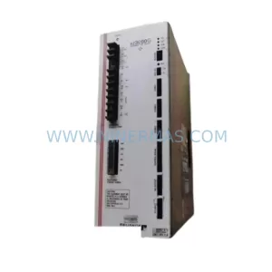
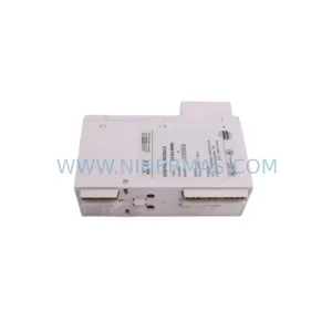
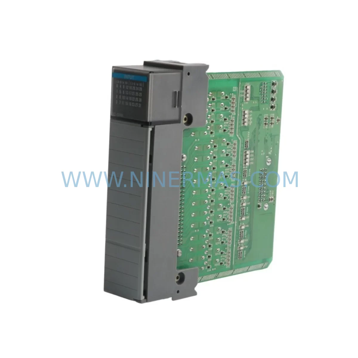
Allen-Bradley 1746-OW4 Retrofit-Compatible Relay Output Module
Verify the part, confirm the platform family, and move straight into quotation with the right commercial details.
RFQ Ready
- SKU1746-OW4
- CategoryPLC & Industrial Automation Modules
- BrandAllen-Bradley
- SupportAvailability, lead time, condition, and shipping coordination
How Buyers Usually Use This Page
- Confirm the exact part number and platform family before sending the quote request.
- Use direct email when quantity, condition, and destination are already defined internally.
- Switch to the broader brand or category archive when you need alternates nearby.
Series Navigation
Move through the most common platform families behind this part.
Product RFQ
Send this part directly for quotation.
Include quantity, required condition, destination country, and target delivery timing. Current reference: Allen-Bradley 1746-OW4 Retrofit-Compatible Relay Output Module with SKU 1746-OW4.
Allen-Bradley 1746-OW4 Retrofit-Compatible Relay Output Module: Legacy System Compatibility & Smooth Upgrade Path
The Allen-Bradley 1746-OW4 is a 4-point relay output module designed for the SLC 500 modular I/O platform. As a retrofit-compatible replacement for aging or discontinued relay output modules in legacy SLC 500 control systems, the 1746-OW4 delivers reliable dry-contact switching for motor starters, solenoid valves, pilot lights, and other field devices operating across a wide voltage range. Whether you are restoring a production line after a module failure, upgrading a control cabinet to extend its operational life, or migrating from an obsolete I/O configuration, the 1746-OW4 provides a proven, drop-in solution that minimizes engineering risk and reduces downtime.
Upgrade Compatibility Table
| Parameter | 1746-OW4 Specification | Retrofit Notes |
|---|---|---|
| Output Type | Relay (dry contact), 4 points | Direct replacement for 1746-OW4 and compatible with legacy relay output slots |
| Output Voltage Range | 5–265V AC/DC | Verify field device voltage before wiring; no additional interface relay required in most cases |
| Output Current | 2A per point (resistive) | Check load current against existing terminal block ratings; re-use existing wiring where possible |
| Backplane Interface | SLC 500 1746 backplane | Compatible with 1746-A4, 1746-A7, 1746-A10, 1746-A13 chassis; confirm slot addressing in RSLogix 500 |
| Communication | SLC 500 backplane protocol | No protocol migration required; module address inherited from slot position |
| Installation Space | Single-slot SLC 500 module | Fits all standard SLC 500 chassis without mechanical modification |
| Replacement Recommendation | Direct drop-in for 1746-OW4 | Confirm I/O map in existing ladder logic; output file O:x.0 bit mapping unchanged |
| Commissioning Focus | Force outputs OFF before insertion | Use RSLogix 500 I/O forcing to verify each relay point before resuming production |
| Warranty | 12-Month Warranty | Covered from date of shipment; includes functional and electrical defect coverage |
Retrofit Planning for Existing Automation Systems
Successful integration of the 1746-OW4 into an existing SLC 500 system begins well before the module arrives on site. Engineers should start by auditing the current chassis configuration. In a typical SLC 500 panel, the 1746-P2 or 1746-P4 power supply feeds the backplane, and its capacity must be verified against the total module load after the retrofit. Adding or replacing modules without checking the power budget is one of the most common causes of intermittent faults after a changeout.
Terminal block wiring is the next critical checkpoint. The 1746-OW4 uses a removable terminal block, which means the existing field wiring can often be transferred directly to the new module without re-labeling or re-routing. However, technicians should inspect each conductor for insulation wear, confirm torque specifications, and verify that the wiring matches the updated I/O drawing before energizing the panel.
In systems where the SLC 500 communicates upstream to a supervisory controller or SCADA system via a 1747-SDN DeviceNet Scanner or a 1747-KE RS-232 Interface Module, the communication link must remain uninterrupted during the module swap. Placing the processor in Program mode and using the 1747-L543 or 1747-L553 SLC 5/04 or 5/05 processor’s online editing capability allows technicians to verify the output file mapping without taking the entire system offline.
For panels that also include analog I/O alongside the relay outputs, the 1746-NI4 analog input module and 1746-NO4I analog output module should be documented in the I/O configuration before any physical changes are made. If the retrofit scope extends to replacing the processor itself, the 1747-L40E SLC 5/04 Ethernet processor is a common upgrade target that preserves the existing 1746 I/O chassis and all installed modules, including the 1746-OW4, while adding modern Ethernet connectivity.
HMI screens connected via a PanelView 550 or PanelView 600 terminal using DH-485 or DF1 protocol should be reviewed to confirm that any output status indicators mapped to the relay module’s output file bits remain valid after the slot reassignment. If the 1746-OW4 is being moved to a different slot during the retrofit, the I/O address must be updated in both the ladder logic program and the HMI tag database before going live.
Signal isolators installed between the 1746-OW4 relay contacts and field devices in hazardous or high-noise environments should be retained and re-verified for compatibility with the new module’s contact ratings. This is particularly important in applications involving variable frequency drives, where relay output chatter can cause nuisance trips if the isolator is not properly specified.
Downtime Control During System Migration
Minimizing production downtime during a relay output module replacement requires a structured approach. The recommended sequence is to perform a full program backup using RSLogix 500 before touching any hardware, saving the .RSS file to a secure location and verifying the backup opens correctly on a programming laptop with the 1747-UIC USB-to-DH-485 interface cable.
With the backup confirmed, the processor should be placed in Program mode and all outputs forced OFF using the RSLogix 500 I/O forcing table. This prevents any unintended actuation of field devices during the physical module swap. The 1746-OW4 can then be removed and replaced with the new module while the chassis remains powered, provided the system design permits hot-swap procedures — always verify this against the specific chassis and power supply documentation before proceeding.
After the new module is seated and the terminal block is reconnected, the technician should use the RSLogix 500 online monitoring mode to verify that each relay output point responds correctly to forced commands before releasing the outputs back to program control. This step-by-step verification protects the original ladder logic from being overwritten and ensures that the field control continuity is maintained throughout the migration. The entire swap, including verification, can typically be completed within a planned maintenance window of 30 to 60 minutes when all materials and documentation are prepared in advance.
For sites where even a brief planned outage is not acceptable, a parallel wiring strategy using a temporary 1746-OW4 installed in a spare chassis slot — if available — allows the new module to be pre-wired and tested before the final cutover, reducing the live changeover to a matter of minutes.
Retrofit Support FAQ
Q: Is the 1746-OW4 a direct replacement for my existing relay output module in the same SLC 500 chassis?
A: Yes. The 1746-OW4 is a single-slot SLC 500 module that installs directly into any 1746-series chassis slot. No mechanical modification is required. Confirm the slot address in your RSLogix 500 program matches the physical slot position before going online.
Q: What commissioning steps are required after installing the replacement module?
A: After seating the module and reconnecting the terminal block, place the processor in Program mode, use RSLogix 500 I/O forcing to test each of the four relay output points individually, verify field device response, then release forcing and return the processor to Run mode. Document each step in your site commissioning record.
Q: How do I verify wiring compatibility between my existing terminal block and the new 1746-OW4?
A: The 1746-OW4 uses a standard removable terminal block. Compare your existing wiring diagram against the 1746-OW4 installation instructions to confirm conductor gauge, torque values, and contact polarity. In most cases, the existing field wiring can be transferred directly without modification.
Q: What warranty and supply assurance does NINERMAS provide for the 1746-OW4?
A: Every 1746-OW4 supplied by NINERMAS carries a 12-month warranty covering functional and electrical defects from the date of shipment. Each unit undergoes pre-shipment functional testing. NINERMAS maintains stock inventory to support urgent retrofit and emergency replacement requirements with short lead times.
| Product Series | SLC 500 |
|---|---|
| Country of Origin | US |
Catalog Continuation
More Allen-Bradley modules in the catalog.
Use the brand lane to compare nearby part numbers, platform-adjacent modules, and other inquiry-ready listings before sending your final RFQ.
Catalog Continuation
Alternative parts within PLC & Industrial Automation Modules.
Stay inside the same system family when you need substitutes, adjacent modules, or a broader shortlist for procurement review.
SKU: PCE-2 LIF-1 K15MB000 671-5532-02
Tektronix PCE-2 LIF-1 K15MB000 671-5532-02 Service-Ready Spare Part