Original Industrial Spare Part
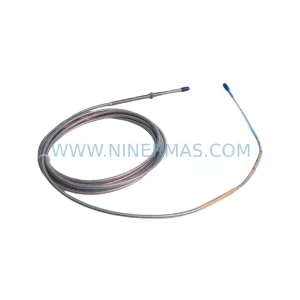
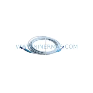
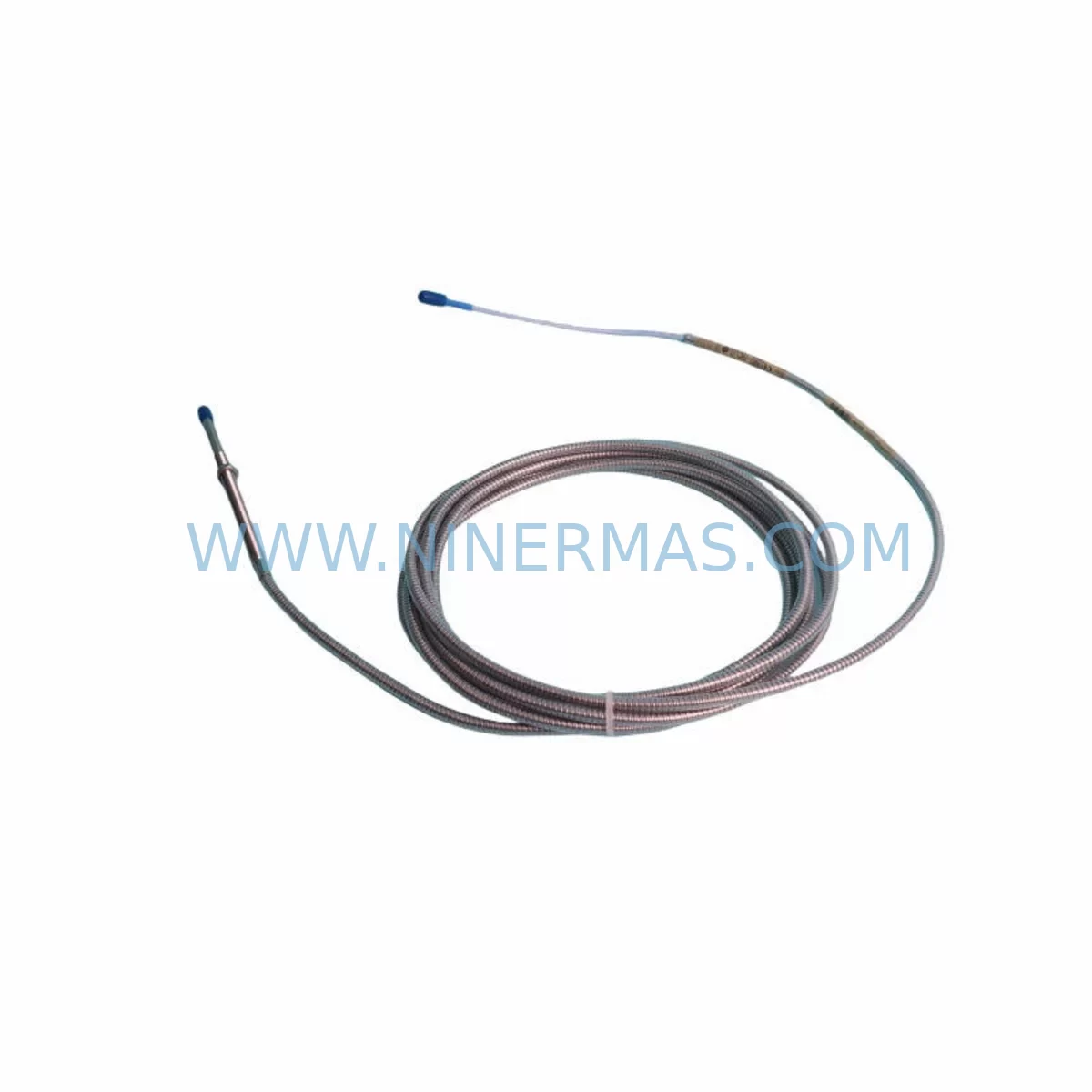
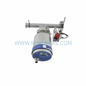
Bently Nevada 330104-06-16-50-02-00 Retrofit Proximity Transducer
Verify the part, confirm the platform family, and move straight into quotation with the right commercial details.
RFQ Ready
- SKU330104-06-16-50-02-00
- CategoryTSI & Rotating Machinery Monitoring
- BrandBently Nevada
- SupportAvailability, lead time, condition, and shipping coordination
How Buyers Usually Use This Page
- Confirm the exact part number and platform family before sending the quote request.
- Use direct email when quantity, condition, and destination are already defined internally.
- Switch to the broader brand or category archive when you need alternates nearby.
Series Navigation
Move through the most common platform families behind this part.
Product RFQ
Send this part directly for quotation.
Include quantity, required condition, destination country, and target delivery timing. Current reference: Bently Nevada 330104-06-16-50-02-00 Retrofit Proximity Transducer with SKU 330104-06-16-50-02-00.
Bently Nevada 330104-06-16-50-02-00 Retrofit-Compatible Proximity Transducer System for Legacy Automation Upgrades
The Bently Nevada 330104-06-16-50-02-00 is an 8mm proximity transducer system designed for continuous shaft vibration and position monitoring in rotating machinery applications. As legacy 3300 Series installations reach end-of-life or face discontinued spare part availability, this unit serves as a direct retrofit-compatible replacement, enabling facilities to extend the operational life of their existing monitoring infrastructure without requiring a full platform migration. Whether you are managing a turbine control panel, a compressor monitoring rack, or a critical pump protection system, the 330104-06-16-50-02-00 integrates into your existing wiring harness and signal conditioning chain with minimal modification.
Upgrade Compatibility Table
| Parameter | Details |
|---|---|
| SKU / Part Number | 330104-06-16-50-02-00 |
| Series | Bently Nevada 3300 XL 8mm Proximity Transducer System |
| Probe Length | 6 inches (152 mm) |
| Cable Length | 16 feet (5 m) integral cable |
| Extension Cable | 50 feet (15 m) — compatible with 330130 series extension cables |
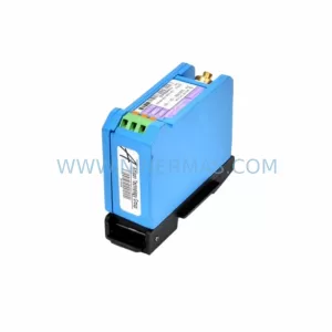
| Driver / Oscillator | Compatible with 3300 XL 8mm driver (e.g. 330180 series) |
| Output Signal | -24 VDC nominal, linear range -10 to -18 VDC |
| Installation Interface | M10 x 1 thread, standard 3300 series mounting bracket |
| Communication Compatibility | Analog 4–20 mA via signal conditioner; compatible with 3500 rack I/O modules |
| Replacement Recommendation | Direct drop-in for 330104-06-16-50-02-00; verify gap voltage and driver pairing |
| Commissioning Focus | Gap voltage calibration, polarity check, signal noise floor verification |
| Warranty | 12 Months from date of shipment |
Retrofit Planning for Existing Automation Systems
When planning a retrofit around the 330104-06-16-50-02-00, the first step is to audit the existing transducer system assembly — probe, extension cable, and driver — as a matched set. The 3300 XL system requires that all three components be sourced from the same calibrated family. If the existing extension cable (such as a 330130-045-00-00) is still within specification, it may be reused, reducing replacement cost and installation time. However, if the cable jacket shows thermal degradation or the connector pins are corroded, full assembly replacement is recommended.
On the rack side, the signal from the 330104-06-16-50-02-00 feeds into a 3500 Series monitoring rack, typically through a 3500/42M or 3500/40M proximitor I/O module. Before swapping the transducer, confirm that the rack’s channel configuration — including gap voltage setpoints, full-scale range, and alarm thresholds — is documented and backed up. Many sites use the System 1 software platform to archive these parameters, and restoring them post-swap is straightforward if the export was completed before shutdown.
For facilities running older 3300 Series racks rather than the 3500 platform, the retrofit path may involve a parallel upgrade of the monitoring rack itself. In this scenario, the 330104-06-16-50-02-00 probe assembly can be installed first, with the driver temporarily connected to the legacy rack to maintain monitoring continuity. Once the new 3500 rack is wired and configured, the driver output is transferred to the new I/O module with no interruption to the probe installation. This staged approach is particularly effective in applications where the machine cannot be taken offline for extended periods.
Terminal wiring at the junction box must be verified against the original as-built drawings. The 330104-06-16-50-02-00 uses a standard coaxial signal path, but the field termination block pinout varies between cabinet generations. Pay close attention to shield grounding — improper shield termination is one of the most common sources of noise in proximity transducer circuits and can cause false vibration alarms or erratic Keyphasor signals. If the existing control cabinet uses a DIN rail terminal block arrangement, confirm that the coaxial-to-terminal adapters are rated for the signal frequency range of the 3300 XL system.
In applications involving I/O expansion or protocol migration — for example, moving from a hardwired relay output to a Modbus RTU or PROFIBUS DP interface — the 330104-06-16-50-02-00 remains compatible as the field sensing element. The protocol conversion is handled upstream at the 3500 rack communication gateway or at a dedicated signal isolator module. Signal isolators from the MTL or P+F families are commonly used in these migration projects to provide galvanic isolation between the legacy field wiring and the new digital communication backbone.
If the retrofit also involves HMI screen updates, ensure that the tag names and engineering unit scaling for the vibration channels are updated to match the new rack configuration. Many facilities discover during commissioning that the HMI faceplate still references the old channel address or uses a scaling factor calibrated for the previous transducer sensitivity. Updating these parameters in the SCADA or DCS configuration before the machine is returned to service prevents nuisance alarms during the initial run-up period.
Downtime Control During System Migration
Minimizing downtime during a proximity transducer retrofit begins with pre-staging all replacement components — probe, extension cable, driver, and any required mounting hardware — at the work site before the machine is taken offline. For the 330104-06-16-50-02-00, this includes verifying that the replacement driver (such as a 330180-X1-05 or equivalent 3300 XL driver) is pre-configured and bench-tested against the probe assembly before installation. A bench gap voltage check using a precision DC voltmeter confirms that the probe-driver pair is within the linear range before the unit is installed in the field.
Program logic protection is equally important. Before disconnecting the existing transducer, confirm that the PLC or DCS has the current ladder logic or function block program archived. If the monitoring rack provides a trip output to the safety system, place the relevant channel in bypass mode according to the site’s management of change procedure. This prevents a spurious machine trip during the swap interval. Once the new 330104-06-16-50-02-00 assembly is installed and the gap voltage is confirmed within specification, the bypass can be removed and the channel returned to normal monitoring mode.
For sites with redundant monitoring channels, the migration can be performed one channel at a time while the redundant channel remains active, effectively reducing the exposure window to zero for critical protection functions. This approach is standard practice in turbine and compressor applications where continuous protection is a regulatory or insurance requirement. Document the as-left gap voltage, sensitivity, and alarm setpoints for each channel before closing the junction box and returning the machine to service.
Retrofit Support FAQ
Q: Is the 330104-06-16-50-02-00 a direct replacement for my existing Bently Nevada 3300 XL probe assembly?
A: Yes. The 330104-06-16-50-02-00 is a direct retrofit-compatible replacement for the 3300 XL 8mm proximity transducer system. Verify that your existing driver and extension cable are from the same 3300 XL family to ensure calibrated system performance. If the full assembly needs replacement, the matching 330130 series extension cable and 330180 series driver are recommended.
Q: What pre-shipment testing is performed on this unit?
A: Each 330104-06-16-50-02-00 unit undergoes functional output verification and gap voltage linearity testing prior to shipment. Units are inspected for connector integrity, cable jacket condition, and thread specification compliance. A test report is available upon request.
Q: How do I confirm wiring compatibility with my existing control cabinet?
A: Compare the terminal block pinout in your existing as-built drawings against the 3300 XL system wiring diagram. The coaxial signal path uses a standard center-conductor/shield arrangement. Confirm shield grounding at one end only to avoid ground loops. If your cabinet uses a barrier terminal block, verify that the impedance rating is compatible with the 3300 XL driver output impedance.
Q: What is the warranty and lead time for the 330104-06-16-50-02-00?
A: This unit carries a 12-month warranty from the date of shipment, covering manufacturing defects and functional performance. In-stock units are available for same-day or next-business-day dispatch. Contact our team to confirm current inventory status and expedited shipping options for urgent retrofit projects.
—
| Product Series | 3300 series |
|---|---|
| Country of Origin | US |
Catalog Continuation
More Bently Nevada modules in the catalog.
Use the brand lane to compare nearby part numbers, platform-adjacent modules, and other inquiry-ready listings before sending your final RFQ.
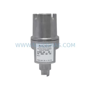
SKU: 21000-00-00-00-064-01-02
Bently Nevada 21000-00-00-00-064-01-02 Service-Ready Spare Part
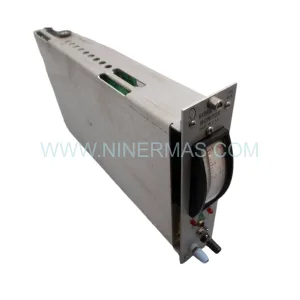
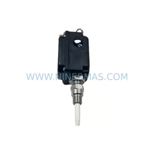
SKU: 330881-16-05-035-01-02
Bently Nevada 330881-16-05-035-01-02 Service-Ready Spare Part
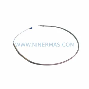
SKU: 330910-00-16-50-02-00
Bently Nevada 330910-00-16-50-02-00 Safety-Reliable Proximity Transducer
Catalog Continuation
Alternative parts within TSI & Rotating Machinery Monitoring.
Stay inside the same system family when you need substitutes, adjacent modules, or a broader shortlist for procurement review.
SKU: DA01A12TGAS20A00 CP4010, FC-226-02 2709-75313 13190869 EVS9322-ES
MKS DA01A12TGAS20A00 Service-Ready Spare Part for Industrial Maintenance