Original Industrial Spare Part
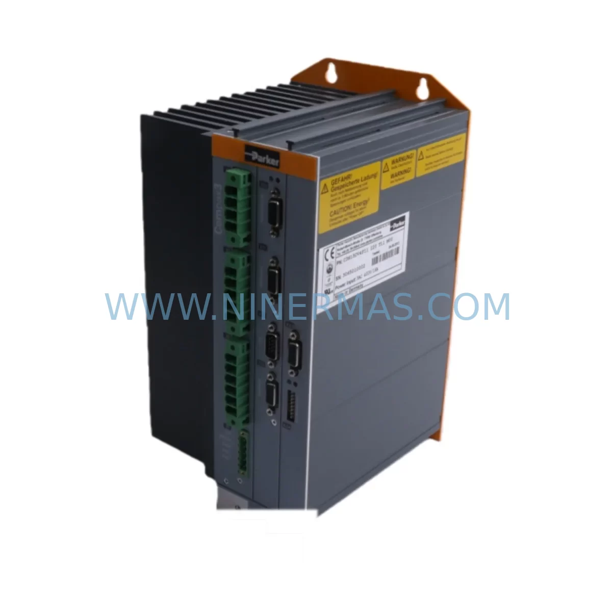
Parker C3S150V4 F10 I20 T40 M11 Retrofit Servo Drive
Verify the part, confirm the platform family, and move straight into quotation with the right commercial details.
RFQ Ready
- SKUC3S150V4 F10 I20 T40 M11
- CategoryPLC & Industrial Automation Modules
- BrandParker
- SupportAvailability, lead time, condition, and shipping coordination
How Buyers Usually Use This Page
- Confirm the exact part number and platform family before sending the quote request.
- Use direct email when quantity, condition, and destination are already defined internally.
- Switch to the broader brand or category archive when you need alternates nearby.
Series Navigation
Move through the most common platform families behind this part.
Product RFQ
Send this part directly for quotation.
Include quantity, required condition, destination country, and target delivery timing. Current reference: Parker C3S150V4 F10 I20 T40 M11 Retrofit Servo Drive with SKU C3S150V4 F10 I20 T40 M11.
Parker C3S150V4 F10 I20 T40 M11 Retrofit Servo Drive: Legacy System Compatible Upgrade
The Parker C3S150V4 F10 I20 T40 M11 is a high-performance servo drive from the Parker Compax3 series, engineered for demanding industrial motion control applications. As legacy automation systems age and original spare parts become increasingly difficult to source, this unit serves as a critical retrofit-compatible replacement for facilities operating older Parker Compax3 platforms. Whether you are managing a planned upgrade or responding to an unplanned failure on the production floor, the C3S150V4 F10 I20 T40 M11 provides a reliable, tested, and immediately deployable solution with a 12-month warranty backed by NINERMAS inventory supply.
The SKU designation C3S150V4 F10 I20 T40 M11 encodes the drive’s key specifications: 150A continuous current rating, 400V AC three-phase input, F10 feedback interface, I20 I/O configuration, T40 technology module, and M11 motion profile. Understanding these parameters is essential when planning a retrofit, as mismatched specifications between the legacy drive and its replacement can result in incompatible terminal wiring, incorrect encoder feedback signals, or communication link failures that extend downtime unnecessarily.
Upgrade Compatibility Table
| Parameter | Legacy / Outgoing Unit | C3S150V4 F10 I20 T40 M11 (Replacement) | Retrofit Notes |
|---|---|---|---|
| Power Input | 3-phase 400V AC (varies) | 3-phase 400V AC | Verify incoming supply voltage and phase sequence before installation |
| Continuous Current | Varies by legacy model | 150A | Confirm motor nameplate current does not exceed drive rating |
| Feedback Interface | F10 (resolver / encoder) | F10 | Encoder cable pinout must be verified against motor feedback connector |
| I/O Configuration | I20 | I20 | Digital and analog I/O terminal mapping should be confirmed against existing PLC wiring diagram |
| Technology Module | T40 | T40 | Ensure technology module firmware version is compatible with existing motion program |
| Communication Protocol | RS-232 / CANopen / PROFIBUS (site-dependent) | Configurable via M11 | Confirm fieldbus protocol and node address settings before commissioning |
| Mounting / Installation | DIN rail or panel mount | Panel mount | Verify cabinet depth and clearance for heat dissipation |
| Programming Interface | Parker Compax3 ServoManager | Parker Compax3 ServoManager | Existing C3 project files can be reloaded; verify axis parameters after download |
| Warranty | N/A (end-of-life) | 12 Months | Covered by NINERMAS 12-month warranty from date of shipment |
Retrofit Planning for Existing Automation Systems
Successful retrofit of the Parker C3S150V4 F10 I20 T40 M11 into an existing control cabinet begins well before the physical swap. Engineers should start by auditing the full drive system, including the Parker motor connected to the drive, the feedback cable assembly, and the power supply module feeding the DC bus. In many legacy Compax3 installations, the 24VDC control power is sourced from a shared rail that also supplies the PLC I/O modules and HMI panel. Before removing the outgoing drive, it is critical to document the terminal block wiring, photograph the existing cable routing, and record all axis parameters from the Parker Compax3 ServoManager software.
The I/O wiring associated with the I20 configuration typically includes digital enable signals, fault relay outputs, and analog reference inputs from the upstream controller. In systems where the PLC — often a Siemens S7-300, Allen-Bradley ControlLogix, or Mitsubishi Q-series — sends velocity or torque references via analog output cards, the signal scaling and offset values must be preserved exactly. Any deviation in the ±10V reference range or the 4–20mA torque command will result in unexpected axis behavior during the first test run.
The T40 technology module embedded in this drive supports advanced motion functions including electronic gearing, cam profiling, and position capture. Facilities that rely on these functions — common in packaging lines, printing machines, and winding applications — must verify that the replacement drive’s T40 firmware version matches or exceeds the version used in the outgoing unit. Downgrading firmware during a retrofit can silently disable motion features that the machine program depends on, leading to faults that are difficult to diagnose without the original project documentation.
For sites using CANopen or PROFIBUS fieldbus communication, the M11 module configuration must be set to match the original node address and baud rate. In multi-axis systems where several Compax3 drives share a single fieldbus segment alongside other devices — such as a Parker ACR9000 motion controller, a Beckhoff EtherCAT coupler, or a Siemens ET 200S distributed I/O station — an incorrect node address will cause bus conflicts that take the entire segment offline. Always use a fieldbus diagnostic tool to verify network integrity before restarting the machine.
Backplane and rack considerations are equally important. In installations where the Compax3 drive is mounted adjacent to a Parker AC890 variable frequency drive or a Parker SSD 690+ drive in a shared cabinet, the physical spacing and airflow path must be re-evaluated after the replacement unit is installed. The C3S150V4 generates significant heat at full load, and inadequate clearance between drives can trigger thermal shutdowns within hours of restart.
Signal isolators are frequently required when integrating the replacement drive into older control architectures. If the existing system uses legacy 0–10V analog signals from a DCS or a standalone motion controller, a signal isolator or signal conditioner between the controller output and the drive analog input will prevent ground loop interference that manifests as axis oscillation or position drift. Similarly, if the encoder feedback signal is shared between the drive and a separate position display or a safety relay module, a line driver splitter should be installed to maintain signal integrity.
Programming cable access is another practical consideration. The Parker Compax3 ServoManager connects to the drive via a dedicated RS-232 serial cable. In modernized control panels where RS-232 ports have been replaced by USB or Ethernet interfaces, a USB-to-RS-232 adapter with the correct driver version is required. Attempting to use an incompatible adapter can result in communication timeouts that prevent parameter upload or download, adding hours to the commissioning process.
Downtime Control During System Migration
Minimizing production downtime during a Compax3 drive replacement requires a structured pre-outage preparation process. The most effective approach is to complete all parameter backup, wiring documentation, and spare parts staging before the maintenance window begins. NINERMAS ships the C3S150V4 F10 I20 T40 M11 with pre-shipment functional testing completed, which eliminates the risk of receiving a non-functional unit and discovering the fault only after the old drive has been removed.
During the outage, the recommended sequence is: isolate and lock out the incoming power supply, discharge the DC bus capacitors, remove the feedback cable and power cables from the outgoing drive, install the replacement unit, reconnect all cables in the documented order, restore control power, and perform a parameter download from the saved ServoManager project file before enabling the power stage. This sequence, when followed precisely, typically allows a trained technician to complete the physical swap in under two hours for a single-axis system.
To protect the original program logic, the PLC program should remain in RUN mode with the axis in a safe, disabled state throughout the drive replacement. This approach preserves the HMI screen states, active recipe parameters, and production counters without requiring a full system restart. Once the replacement drive is online and communicating on the fieldbus, a controlled jog test at reduced speed should be performed before returning the axis to automatic mode. Any deviation in position feedback, velocity response, or torque limit behavior should be investigated and corrected before resuming production.
For facilities with strict SIL or safety relay requirements, the safety function wiring — typically connected to the STO (Safe Torque Off) terminals — must be verified with a functional safety test after every drive replacement, regardless of whether the wiring was disturbed. This step is non-negotiable and should be documented in the maintenance record.
Retrofit Support FAQ
Q: Is the Parker C3S150V4 F10 I20 T40 M11 a direct drop-in replacement for my existing Compax3 drive?
A: In most cases, yes. The C3S150V4 F10 I20 T40 M11 is designed as a form-fit-function replacement within the Compax3 series. However, you should verify the power rating, feedback type, I/O configuration, and technology module version against your existing installation before ordering. NINERMAS technical support can assist with compatibility verification based on your existing drive nameplate data.
Q: What commissioning steps are required after installing the replacement drive?
A: After physical installation, you will need to download the saved ServoManager project file to the replacement drive, verify all axis parameters including encoder resolution, current limits, and velocity limits, confirm fieldbus node address and baud rate settings, perform a low-speed jog test, and complete a safety function verification if STO wiring is present. NINERMAS provides pre-shipment functional test documentation to confirm the drive was operational before dispatch.
Q: Does NINERMAS provide a warranty on this unit?
A: Yes. All Parker C3S150V4 F10 I20 T40 M11 units supplied by NINERMAS carry a 12-month warranty from the date of shipment. The warranty covers manufacturing defects and functional failures under normal operating conditions. Units that show evidence of incorrect installation, overvoltage, or physical damage are not covered. Contact sale@ninermas.com for warranty claims or technical support.
Q: What is the typical lead time and stock availability?
A: NINERMAS maintains inventory of the C3S150V4 F10 I20 T40 M11 to support urgent replacement requirements. Standard orders are processed and shipped within 1–3 business days. For large quantity orders or scheduled maintenance programs, contact our sales team to confirm stock levels and arrange priority allocation. Emergency same-day dispatch may be available for critical production line failures — contact +0086 187 5021 5667 for urgent requirements.
| Product Series | Other series |
|---|
Catalog Continuation
Nearby part numbers around C3S150V4.
Use this lane when the buyer is comparing adjacent model numbers, revision-near items, or closely related spare variants within the same brand family.
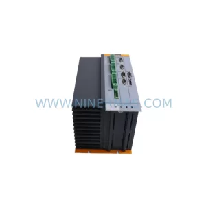
SKU: C3S150V4F11 I20 T11 M00
Parker C3S150V4F11 I20 T11 M00 Retrofit-Compatible Servo Drive
Catalog Continuation
More Parker modules in the catalog.
Use the brand lane to compare nearby part numbers, platform-adjacent modules, and other inquiry-ready listings before sending your final RFQ.
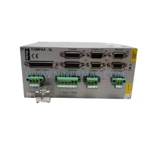
SKU: CPX1000SL/F5/CG
Parker CPX1000SL/F5/CG Safety-Reliable Valve Controller
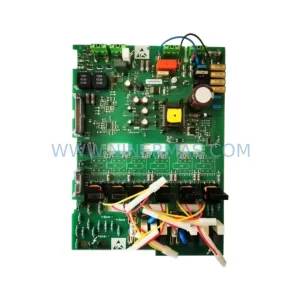
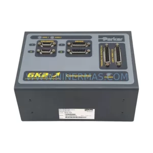
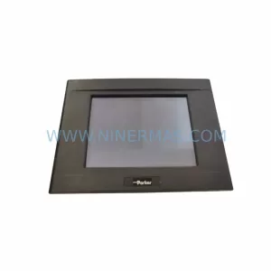
SKU: 6K2-NK 1061926
Parker 6K2-NK 1061926 Spare Part for Industrial Maintenance
Catalog Continuation
Alternative parts within PLC & Industrial Automation Modules.
Stay inside the same system family when you need substitutes, adjacent modules, or a broader shortlist for procurement review.
SKU: HDD02.2-W040N-HS12-01-FW FWA-DIAX04-ELS-05VRS-MS
Rexroth HDD02.2-W040N-HS12-01-FW Service-Ready Spare Part
SKU: I5DAE375F10010000S
Lenze I5DAE375F10010000S Service-Ready Spare Part for Industrial Maintenance