Original Industrial Spare Part
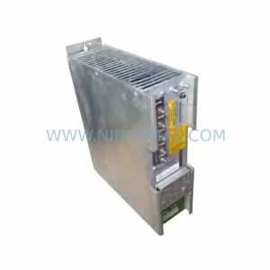
Parker C3S150V4F11 I20 T11 M00 Retrofit-Compatible Servo Drive
Verify the part, confirm the platform family, and move straight into quotation with the right commercial details.
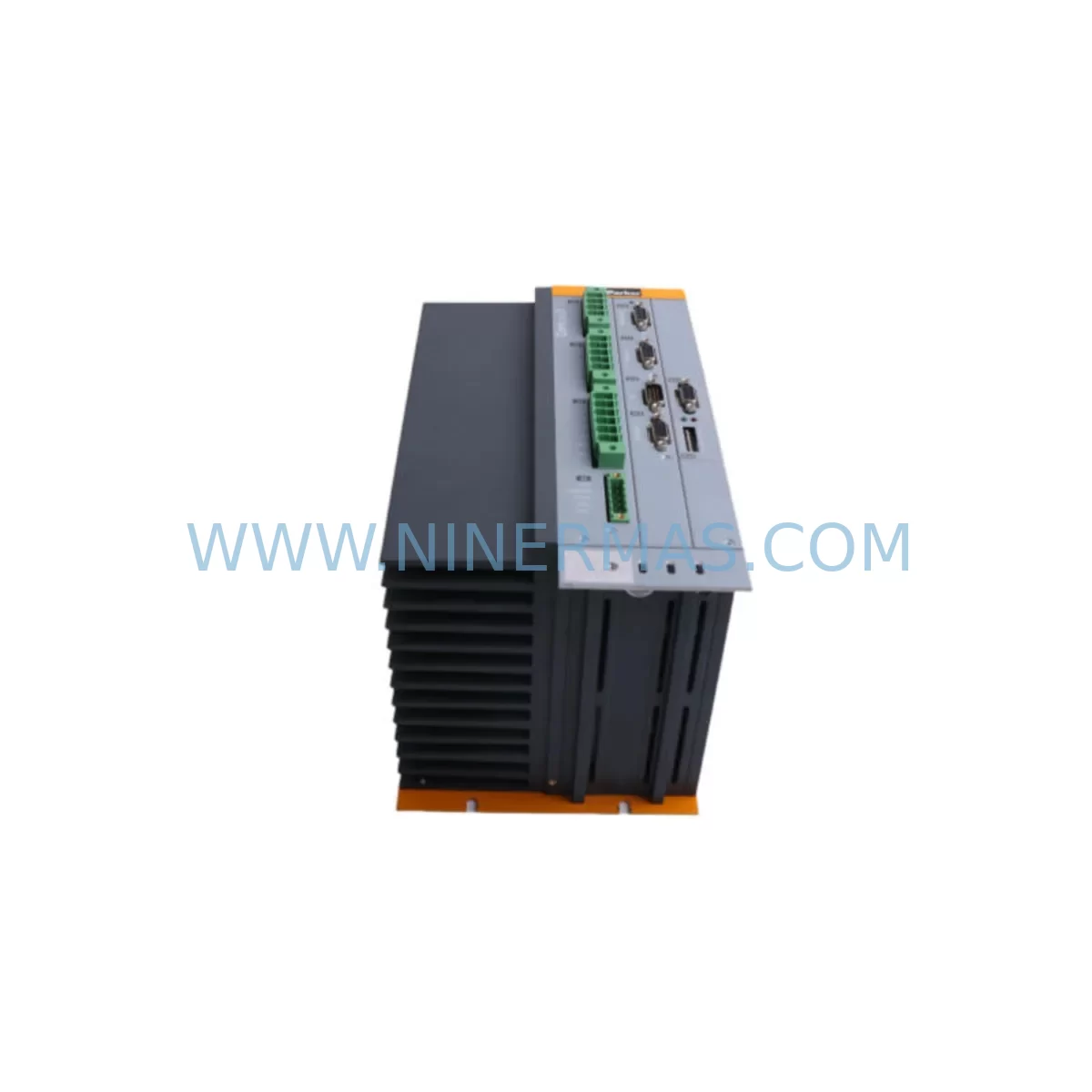
RFQ Ready
- SKUC3S150V4F11 I20 T11 M00
- CategoryPLC & Industrial Automation Modules
- BrandParker
- SupportAvailability, lead time, condition, and shipping coordination
How Buyers Usually Use This Page
- Confirm the exact part number and platform family before sending the quote request.
- Use direct email when quantity, condition, and destination are already defined internally.
- Switch to the broader brand or category archive when you need alternates nearby.
Series Navigation
Move through the most common platform families behind this part.
Product RFQ
Send this part directly for quotation.
Include quantity, required condition, destination country, and target delivery timing. Current reference: Parker C3S150V4F11 I20 T11 M00 Retrofit-Compatible Servo Drive with SKU C3S150V4F11 I20 T11 M00.
Parker C3S150V4F11 I20 T11 M00 Retrofit-Compatible Servo Drive for Legacy Systems
The Parker C3S150V4F11 I20 T11 M00 is a Compax3 series servo drive engineered for demanding industrial environments. As legacy Parker motion control platforms approach end-of-life, this unit serves as a verified retrofit-compatible replacement for discontinued servo drive modules across a wide range of production lines, control cabinets, and multi-axis automation systems. Whether you are managing a planned upgrade or responding to an unplanned failure, the C3S150V4F11 I20 T11 M00 provides a reliable, drop-in-compatible solution with full support for existing wiring configurations, feedback interfaces, and communication protocols.
The Compax3 platform — including the C3S150V4F11 I20 T11 M00 — is widely deployed in packaging machinery, press lines, material handling systems, and precision assembly equipment. When original units become unavailable through standard distribution channels, sourcing a verified replacement with confirmed firmware compatibility and tested I/O mapping is critical to maintaining production continuity and avoiding extended downtime.
Upgrade Compatibility Table
| Parameter | Specification | Retrofit Notes |
|---|---|---|
| SKU / Model | C3S150V4F11 I20 T11 M00 | Verify full model string before ordering; suffix codes define I/O, feedback, and communication options |
| Series | Parker Compax3 | Compatible with existing Compax3 rack and backplane infrastructure |
| Power Rating | 150 W continuous | Confirm cabinet power supply capacity; check Parker CPX2500 or equivalent DC bus supply rating |
| Feedback Interface (F11) | Resolver / Encoder (F11 type) | Match feedback cable pinout to motor encoder connector; re-use existing resolver wiring where possible |
| I/O Configuration (I20) | Digital I/O expansion set | Verify terminal block assignments against original wiring diagram; re-map if I/O addresses differ |
| Communication (T11) | RS-232 / CANopen interface | Confirm baud rate, node address, and protocol settings match existing PLC or motion controller configuration |
| Option Module (M00) | No option module fitted | If original unit had an option module, source separately (e.g., PROFIBUS or DeviceNet expansion) |
| Installation Footprint | Standard Compax3 single-slot | Confirm DIN rail or panel mounting space; check adjacent module clearance for airflow |
| Programming Interface | Parker C3 ServoManager software | Use EPR-C3 programming cable to upload and verify axis parameters before commissioning |
| Warranty | 12-Month Warranty | All units ship with 12-month warranty; outgoing test report available on request |
Retrofit Planning for Existing Automation Systems
Successful integration of the Parker C3S150V4F11 I20 T11 M00 into an existing automation system requires a structured pre-installation review. Begin by auditing the control cabinet layout to confirm available slot positions on the Compax3 backplane. In multi-axis configurations, the C3S150V4F11 I20 T11 M00 typically shares a DC bus with adjacent drives such as the Parker C3S075V4F10 (lower-power axis) or the Parker C3S300V4F12 (higher-torque axis), and the total bus load must remain within the rated capacity of the system power supply — commonly a Parker CPX2500 DC bus supply or equivalent regenerative unit.
Terminal wiring is a critical checkpoint. The I20 digital I/O configuration uses a defined terminal block layout; cross-reference the original wiring diagram against the replacement unit’s terminal assignment table before energizing. Signal isolation may be required at the interface between the servo drive and field devices — a DIN-rail-mounted signal isolator or relay module can protect the drive’s I/O from voltage transients common in older panel wiring.
For communication continuity, the T11 interface (RS-232 / CANopen) must be configured to match the node address and baud rate of the existing motion network. If the upstream controller is a Parker Compax3T40 multi-axis controller or a third-party PLC communicating via CANopen, verify that the new drive’s node ID does not conflict with other devices on the bus. A Parker C3I011 I/O expansion module may be present in the same cabinet and must remain addressed correctly after the drive swap.
Before final commissioning, upload the saved axis parameter set using the EPR-C3 programming cable and Parker C3 ServoManager. Confirm that motor data, encoder resolution, current limits, and velocity profiles match the original configuration. If the system includes an HMI panel displaying axis status or fault codes, verify that the HMI screen tags still map correctly to the drive’s communication objects after the replacement. A Parker C3F250 line filter installed upstream of the drive should be inspected and replaced if it shows signs of thermal stress or insulation degradation.
For systems requiring 24 VDC logic supply, confirm that the existing Parker PS90 or equivalent control power supply can support the inrush current of the replacement drive during initialization. In cabinets with tight power budgets, stagger the power-on sequence of multiple Compax3 axes to avoid simultaneous inrush events.
Downtime Control During System Migration
Minimizing production downtime during a servo drive replacement requires advance preparation and a disciplined commissioning sequence. Before removing the failed or end-of-life unit, use the EPR-C3 programming cable to export a full backup of the axis parameter file from the existing drive if it is still partially functional. Store this backup on a dedicated engineering laptop alongside the original project file from the Parker C3 ServoManager archive.
Physically label all terminal connections and communication cables before disconnection. Photograph the wiring layout from multiple angles. In systems where the C3S150V4F11 I20 T11 M00 controls a critical axis — such as a feed roll, clamping cylinder, or indexing table — coordinate the replacement window with production scheduling to align with a planned maintenance shift rather than an emergency response.
Once the replacement unit is installed and wired, perform a low-speed jog test before enabling full-speed operation. Verify encoder feedback signal quality, check for drive fault codes, and confirm that the PLC or Compax3T40 controller acknowledges the axis as ready. If the system uses a safety relay or STO (Safe Torque Off) circuit, test the safety function before returning the machine to automatic mode. Document the commissioning results and retain the outgoing test report supplied with the unit for traceability.
With a verified replacement unit in stock and a pre-prepared parameter backup, most Compax3 axis replacements can be completed within a single maintenance window, keeping unplanned downtime to a minimum and protecting the integrity of the surrounding control logic.
Retrofit Support FAQ
Q1: Is the C3S150V4F11 I20 T11 M00 a direct replacement for my existing Compax3 servo drive?
A: The C3S150V4F11 I20 T11 M00 is a direct form-fit-function replacement for units with the same model suffix. Confirm that the feedback type (F11), I/O configuration (I20), communication interface (T11), and option module code (M00) all match your original unit. Differences in any suffix code indicate a different hardware configuration that may require wiring or parameter adjustments.
Q2: Can I reuse my existing motor cables and encoder wiring?
A: In most cases, yes. The Compax3 platform uses standardized connector pinouts for motor power and feedback cables. Verify the feedback cable pinout against the F11 interface specification before reconnection. If the original cable shows insulation wear or connector damage, replace it during the same maintenance window to avoid a secondary failure.
Q3: What commissioning steps are required after installation?
A: After mechanical installation and wiring, connect the EPR-C3 programming cable and use Parker C3 ServoManager to load the saved axis parameter file. Verify motor data, current limits, and communication settings. Perform a low-speed jog test, check for fault codes, and confirm HMI tag mapping before returning the axis to automatic operation. An outgoing test report is available on request to confirm factory-level verification.
Q4: What is the warranty and stock availability?
A: All Parker C3S150V4F11 I20 T11 M00 units supplied by NINERMAS carry a 12-month warranty covering manufacturing defects and functional performance. Stock is maintained for immediate dispatch to support urgent retrofit and breakdown replacement requirements. Contact our team to confirm current inventory levels and lead times for your project.
| Product Series | Other series |
|---|
Catalog Continuation
More Parker modules in the catalog.
Use the brand lane to compare nearby part numbers, platform-adjacent modules, and other inquiry-ready listings before sending your final RFQ.
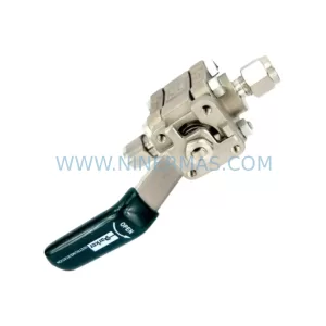
SKU: 016-80686-0 R1E02 2512 A1
Parker 016-80686-0 R1E02 2512 A1 Retrofit Safety Relief Module
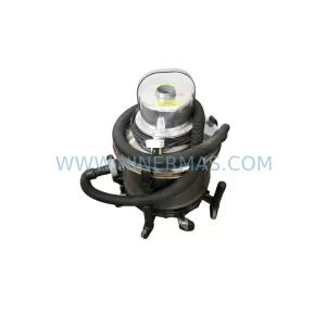
SKU: 605-Z-230CE 0190-08538 CDN127-4 114RR-BJ-000-000
Parker 605-Z-230CE-0190 Retrofit DC Drive for Legacy Systems
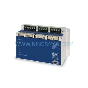
SKU: 890CS-532320B0--B00-U
Parker 890CS-532320B0-B00-U Retrofit Drive for Legacy Systems
Catalog Continuation
Alternative parts within PLC & Industrial Automation Modules.
Stay inside the same system family when you need substitutes, adjacent modules, or a broader shortlist for procurement review.
SKU: TRY/PRG/4-20MA/10-30DC
MOORE TRY/PRG/4-20MA/10-30DC Service-Ready Spare Part
SKU: 5085-404901-11 12INCH 2910-202413-12 404200XRMPD2H14 7-249717
TEL 5085-404901-11 Service-Ready Spare Part for Industrial Maintenance
SKU: DIP011 05-058-011
SIGMATEK DIP011 05-058-011 Service-Ready Spare Part