Original Industrial Spare Part
R. STAHL 9470/32-16-11-C1174 Retrofit-Compatible Analog Module
Verify the part, confirm the platform family, and move straight into quotation with the right commercial details.
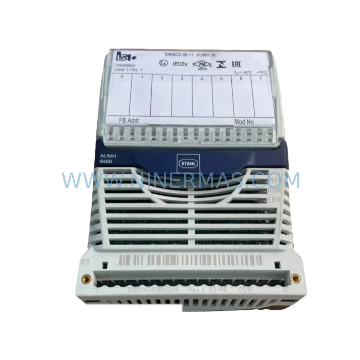
RFQ Ready
- SKU9470/32-16-11-C1174
- CategoryPLC & Industrial Automation Modules
- BrandR. STAHL
- SupportAvailability, lead time, condition, and shipping coordination
How Buyers Usually Use This Page
- Confirm the exact part number and platform family before sending the quote request.
- Use direct email when quantity, condition, and destination are already defined internally.
- Switch to the broader brand or category archive when you need alternates nearby.
Series Navigation
Move through the most common platform families behind this part.
Product RFQ
Send this part directly for quotation.
Include quantity, required condition, destination country, and target delivery timing. Current reference: R. STAHL 9470/32-16-11-C1174 Retrofit-Compatible Analog Module with SKU 9470/32-16-11-C1174.
R. STAHL 9470/32-16-11-C1174 Retrofit-Compatible Analog Module for Legacy System Modernization
The R. STAHL 9470/32-16-11-C1174 is a ruggedized analog I/O module engineered for deployment in hazardous and classified areas, and it remains one of the most sought-after components for engineers undertaking legacy control system retrofits, discontinued spare part replacements, and control cabinet upgrades in process industries. Whether you are migrating an aging DCS platform, restoring a decommissioned safety loop, or extending the service life of an existing intrinsically safe barrier network, the 9470/32-16-11-C1174 provides a reliable, field-proven solution that minimizes engineering rework and reduces total downtime during transition.
As a member of R. STAHL’s 9470 series — a platform widely adopted across oil and gas, chemical processing, pharmaceutical manufacturing, and offshore installations — this module is designed to interface directly with legacy backplane architectures and terminal wiring configurations that engineers have relied upon for decades. Its compatibility with existing I/O channel assignments, signal ranges, and power supply rails makes it an ideal drop-in replacement for discontinued analog modules from earlier generations of the same platform, significantly reducing the need for panel rewiring or PLC program restructuring.
Upgrade Compatibility Table
| Parameter | Details / Retrofit Notes |
|---|---|
| SKU / Part Number | 9470/32-16-11-C1174 |
| Series | R. STAHL 9470 Series |
| Module Type | Ruggedized Analog I/O Module |
| Installation Interface | Compatible with 9470-series backplane and DIN-rail mounting configurations |
| Signal Compatibility | 4–20 mA / 0–10 V analog signal ranges (industry standard) |
| Communication Compatibility | Supports legacy fieldbus and point-to-point wiring topologies |
| Power Supply Requirements | Verify existing rail voltage (typically 24 VDC); confirm current draw against existing PSU capacity |
| Terminal Wiring | Confirm terminal block pitch and conductor cross-section before installation |
| Replacement Recommendation | Direct replacement for discontinued 9470-series analog modules; verify channel count and signal type |
| Commissioning Notes | Re-verify module address, I/O mapping, and HMI tag assignments after swap |
| Warranty | 12-Month Warranty — all units ship after functional bench test |
Retrofit Planning for Existing Automation Systems
Successful integration of the R. STAHL 9470/32-16-11-C1174 into an existing control architecture requires a structured pre-installation assessment. Engineers should begin by auditing the current power supply module — typically a 24 VDC unit mounted within the same control cabinet — to confirm that sufficient current headroom exists to support the replacement analog module alongside any co-installed components such as digital input modules, relay output modules, or communication gateway cards already drawing from the same rail.
Terminal wiring is a critical checkpoint. The existing field cable terminations, including shielded twisted-pair conductors routed from transmitters, control valves, or temperature elements, must be verified against the module’s terminal block layout. In many retrofit scenarios involving older 9470-series installations, the original wiring documentation may be incomplete or reflect field modifications made during earlier maintenance cycles. A physical point-to-point continuity check is strongly recommended before powering the replacement module.
Backplane interface compatibility is another key consideration. The 9470/32-16-11-C1174 is designed to seat into the standard 9470-series rack and backplane assembly. However, engineers should confirm that the backplane connector pins are free of corrosion or mechanical damage — particularly in installations that have operated in high-humidity or chemically aggressive environments. In cases where the backplane itself has reached end of service life, a concurrent backplane replacement using a compatible 9470-series rack unit may be advisable to avoid repeat failures.
Module addressing must be re-established after physical installation. Depending on the host controller — which may be a legacy programmable logic controller or a distributed control system node — the I/O module address is typically set via DIP switches, rotary selectors, or software configuration through the engineering workstation. Confirm that the address assigned to the replacement module matches the original configuration to prevent I/O mapping conflicts that could trigger process alarms or cause the controller to enter a fault state.
Program compatibility should be validated at the function block or ladder logic level. In most cases, a like-for-like analog module replacement within the same 9470 series does not require PLC program modification, provided the channel count, signal type, and scaling parameters are identical. However, if the replacement module introduces any differences in resolution, update rate, or diagnostic behavior, the control program — and any associated HMI screen tag bindings — should be reviewed and updated accordingly. HMI graphics that display analog process values, trend histories, or alarm setpoints tied to the replaced module’s I/O tags should be verified for correct data linkage after commissioning.
Communication link integrity should also be confirmed. In systems where the 9470-series analog module participates in a fieldbus segment — such as PROFIBUS DP, HART multiplexer networks, or proprietary R. STAHL communication protocols — the bus termination, node address, and GSD/device description file configuration should be re-validated post-installation. Signal isolation modules or intrinsic safety barriers installed upstream of the analog inputs may also require recalibration if they were matched to the characteristics of the original module.
Installation space confirmation is essential in densely populated control cabinets. Verify that the replacement module’s physical dimensions, including depth behind the backplane and any protruding connector housings, are compatible with the available cabinet depth and adjacent component clearances. Adequate ventilation spacing should be maintained to prevent thermal derating of the module or neighboring components such as power supply units, surge protection devices, or programming cable interface ports.
Downtime Control During System Migration
Minimizing production downtime during a control system migration involving the R. STAHL 9470/32-16-11-C1174 requires careful pre-staging and a disciplined cutover procedure. Before the scheduled maintenance window, the replacement module should be bench-tested using a portable signal simulator to verify that all analog channels respond correctly across the full input range. This pre-shipment functional test — which NINERMAS performs on every unit prior to dispatch — provides a baseline confidence level that eliminates the risk of receiving a non-functional module on the day of the planned outage.
To protect the original control program logic, a full backup of the PLC or DCS project file should be exported and stored on an offline engineering workstation before any hardware is disturbed. This backup should include all I/O configuration data, function block parameters, alarm setpoint tables, and HMI project files. In the event that the cutover encounters an unexpected compatibility issue, this backup enables rapid restoration of the previous configuration without requiring manual re-entry of process parameters.
Field control continuity can be maintained during the module swap by placing the affected control loops in manual mode at the operator station prior to beginning the physical replacement. Process operators should be briefed on the expected duration of the maintenance window and the manual setpoints to be held during the transition. For critical loops — such as pressure control, flow regulation, or temperature management — a pre-agreed safe operating range should be documented and communicated to the field team before work begins.
After the replacement module is installed and addressed, a staged recommissioning sequence should be followed: power on the module, verify diagnostic LEDs, confirm I/O channel mapping in the controller, perform a live signal check against a known field transmitter output, and then return each control loop to automatic mode individually while monitoring for process stability. This incremental approach reduces the risk of simultaneous multi-loop disturbances and allows the commissioning engineer to isolate any anomalies to a specific channel or configuration parameter.
Retrofit Support FAQ
Q1: Is the R. STAHL 9470/32-16-11-C1174 a direct replacement for discontinued 9470-series analog modules?
In most cases, yes. The 9470/32-16-11-C1174 is designed to maintain physical and electrical compatibility with the standard 9470-series backplane and terminal wiring interface. However, engineers should confirm channel count, signal type (current vs. voltage), and any application-specific configuration options against the original module’s datasheet before finalizing the replacement order.
Q2: What commissioning steps are required after installing the replacement module?
After physical installation, re-establish the module address, verify I/O channel mapping in the host controller, perform a live signal check on all active analog channels, and confirm HMI tag bindings and alarm setpoints. If the module participates in a fieldbus network, re-validate bus configuration and node address assignments.
Q3: Does NINERMAS test units before shipment?
Yes. Every R. STAHL 9470/32-16-11-C1174 unit dispatched by NINERMAS undergoes a functional bench test prior to shipment to confirm analog channel performance across the rated signal range. All units are covered by a 12-month warranty from the date of delivery.
Q4: What is the typical lead time and stock availability?
NINERMAS maintains inventory of the R. STAHL 9470/32-16-11-C1174 to support urgent retrofit and breakdown replacement requirements. Contact our sales team for real-time stock confirmation and expedited shipping options. We supply globally and can provide documentation packages including test reports and material certifications upon request.
| Product Series | Other series |
|---|
Catalog Continuation
More R. STAHL modules in the catalog.
Use the brand lane to compare nearby part numbers, platform-adjacent modules, and other inquiry-ready listings before sending your final RFQ.
SKU: 9468/32-08-11-C1174
R. STAHL 9468/32-08-11-C1174 Service-Ready Spare Part
Catalog Continuation
Alternative parts within PLC & Industrial Automation Modules.
Stay inside the same system family when you need substitutes, adjacent modules, or a broader shortlist for procurement review.
SKU: SC34.0300.0011.0000.0-JW1 SC34.0300.0011.0000.0
LUST SC34.0300.0011.0000.0-JW1 Service-Ready Spare Part
SKU: LSC-096-2-30-560-P5B0H2MM0
LTi Motion LSC-096-2-30-560-P5B0H2MM0 Retrofit Servo Drive
SKU: DS200SHVMG1AFE
GE DS200SHVMG1AFE Retrofit-Compatible Interface Module