Original Industrial Spare Part
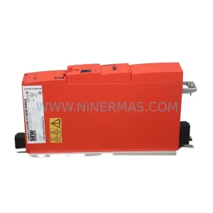
SEW MM11D-503-00 Retrofit-Compatible Drive for Legacy Systems
Verify the part, confirm the platform family, and move straight into quotation with the right commercial details.
RFQ Ready
- SKUMM11D-503-00
- CategoryPLC & Industrial Automation Modules
- BrandSEW-EURODRIVE
- SupportAvailability, lead time, condition, and shipping coordination
How Buyers Usually Use This Page
- Confirm the exact part number and platform family before sending the quote request.
- Use direct email when quantity, condition, and destination are already defined internally.
- Switch to the broader brand or category archive when you need alternates nearby.
Series Navigation
Move through the most common platform families behind this part.
Product RFQ
Send this part directly for quotation.
Include quantity, required condition, destination country, and target delivery timing. Current reference: SEW MM11D-503-00 Retrofit-Compatible Drive for Legacy Systems with SKU MM11D-503-00.
SEW MM11D-503-00 Retrofit-Compatible Drive for Legacy Systems
The SEW-Eurodrive MM11D-503-00 is a decentralized variable speed drive from the MOVIMOT series, engineered for direct motor mounting in distributed automation architectures. As legacy production lines age and original SEW MOVIMOT units reach end-of-life, the MM11D-503-00 has become one of the most sought-after retrofit-compatible spare parts for engineers tasked with modernizing conveyor systems, material handling lines, and intralogistics platforms without full system replacement.
NINERMAS maintains verified stock of the MM11D-503-00 with a 12-month warranty, pre-shipment functional testing, and documented traceability — critical requirements for procurement teams managing spare parts lifecycle programs across multi-site industrial facilities.
Upgrade Compatibility Table
| Parameter | MM11D-503-00 Specification | Retrofit Notes |
|---|---|---|
| Series | MOVIMOT (MM) | Direct replacement within MOVIMOT generation |
| Power Rating | 1.1 kW (inferred from MM11D designation) | Verify motor nameplate; confirm load profile before swap |
| Supply Voltage | 3 × 380–500 V AC, 50/60 Hz | Confirm site voltage tolerance; check incoming supply quality |
| Communication Interface | RS-485 / MOVIBUS fieldbus | Compatible with existing MOVIBUS wiring; verify baud rate settings |
| Terminal Wiring | Standard MOVIMOT terminal block layout | Re-use existing cable harness; inspect insulation before reconnection |
| Mounting Interface | Direct motor flange mount (IEC standard) | Confirm motor flange dimensions; no adapter plate required for same-generation motors |
| Installation Space | Compact decentralized housing | Measure clearance for heat dissipation; minimum 50 mm side clearance recommended |
| Parameter Compatibility | MOVITOOLS MotionStudio / MOVIMOT parameter set | Back up existing parameter set via MOVITOOLS before replacement |
| Commissioning Tool | PC with MOVITOOLS MotionStudio + USB11A or UWS21B cable | Restore saved parameter file post-installation; verify ramp times and speed limits |
| Warranty | 12-Month Warranty — covered from date of shipment by NINERMAS COMPANY LIMITED | |
Retrofit Planning for Existing Automation Systems
When integrating the MM11D-503-00 into an existing MOVIMOT-based line, the retrofit scope extends well beyond the drive unit itself. Engineers must audit the full drive chain: the MOVIMOT MM fieldbus gateway (such as the MF../1 or MQ../1 gateway modules) that bridges the MOVIBUS segment to the upstream PLC must be confirmed operational, as a failing gateway can mask drive faults and complicate commissioning. Similarly, the SEW DFP21B PROFIBUS option card or equivalent fieldbus interface fitted to the master controller should be verified for firmware compatibility with the replacement drive’s parameter set.
On the power supply side, the 24 V DC control voltage rail feeding the MOVIMOT logic board must be stable within ±10% tolerance. If the existing SITOP PSU100S 24 V power supply or equivalent DIN-rail unit is aging, this is an ideal time to replace it in parallel with the drive swap — a failing control supply is a common root cause of intermittent MOVIMOT faults that are often misdiagnosed as drive failures.
Terminal wiring adaptation is straightforward for same-generation MOVIMOT replacements: the standard 5-pin power connector and the 4-pin MOVIBUS connector follow the same pinout across the MM series. However, if the legacy installation used an older MM03D or MM07D variant, engineers should cross-reference the terminal assignment diagram in the MOVIMOT system manual (SEW publication 10974217) to confirm brake control wiring, as the brake rectifier integration differs between sub-variants.
For sites running mixed SEW ecosystems — for example, a combination of MOVIMOT decentralized drives alongside centralized MOVIDRIVE MDX60B/61B cabinet drives or MOVITRAC B frequency inverters — the MM11D-503-00 retrofit does not affect the centralized drive segments. However, if the MOVIBUS segment shares a common RS-485 trunk with other nodes, the node address of the replacement unit must be set to match the original before powering up, to avoid address conflicts that can freeze the entire fieldbus segment.
I/O expansion requirements should also be reviewed: if the legacy system relied on a DIO11B digital I/O option or an analog setpoint input via the DAE11B analog input module, confirm these accessories are present and correctly wired on the replacement unit. Missing I/O options are a frequent cause of post-retrofit commissioning delays. Where the control cabinet houses a MOVI-PLC DHP11B or similar motion controller coordinating multiple MOVIMOT axes, the PLC program’s axis mapping table should be reviewed to ensure the replacement drive’s node address and parameter set align with the programmed axis configuration.
HMI screens connected via the upstream SIMATIC S7 or equivalent PLC should display normal drive status within one scan cycle of successful commissioning. If the HMI shows persistent fault codes after parameter restore, check the UWS21B serial interface adapter connection and re-run the MOVITOOLS parameter download sequence. Signal isolators on analog feedback loops — particularly Phoenix Contact MINI MCR-SL or equivalent DIN-rail isolators — should be inspected for drift if the system has been idle during the retrofit window.
Downtime Control During System Migration
Minimizing production downtime during a MOVIMOT drive replacement requires a structured pre-outage preparation protocol. Before the maintenance window opens, the existing MM11D-503-00 (or its predecessor) parameter set must be uploaded and saved using MOVITOOLS MotionStudio. This backup file — typically a .mup project file — preserves all ramp times, speed limits, brake application delays, and fieldbus node settings, allowing the replacement unit to be configured offline before the line is stopped.
The physical swap itself is typically achievable within 30–60 minutes for a trained technician: disconnect the MOVIBUS connector and power terminals, unbolt the drive from the motor flange, mount the replacement MM11D-503-00, reconnect terminals in reverse order, and restore the parameter file. The critical path item is parameter verification — do not release the line to production until a full speed ramp test (no-load, then loaded) confirms that acceleration and deceleration profiles match the original system behavior.
To protect original program logic in the upstream PLC, place the affected axis in manual/local mode before disconnecting the drive. This prevents the PLC from generating cascading fault states that could affect adjacent axes or trigger emergency stop sequences across the line. Where the MOVIMOT segment feeds a conveyor zone controlled by a Siemens S7-300 or S7-1200 safety PLC, confirm with the safety engineer that the STO (Safe Torque Off) channel is correctly re-enabled after the drive swap, as some safety configurations require a manual reset of the safety relay output before the drive will accept run commands.
Post-commissioning, run the line at reduced speed (typically 20–30 Hz) for the first 15–30 minutes of production to confirm thermal stability and verify that no intermittent fieldbus communication errors appear in the PLC diagnostic buffer. Document the commissioning date, parameter file version, and technician sign-off for the spare parts lifecycle record — a requirement for ISO 9001-compliant maintenance programs and a prerequisite for warranty claim processing under NINERMAS’s 12-month warranty policy.
Retrofit Support FAQ
Q1: Is the MM11D-503-00 a direct drop-in replacement for older MOVIMOT MM series drives?
For same-generation MOVIMOT MM variants with identical power ratings, the MM11D-503-00 is a direct mechanical and electrical replacement. Terminal pinouts, flange dimensions, and MOVIBUS communication protocol are consistent across the MM series. Parameter migration via MOVITOOLS MotionStudio is required; hardware modifications are not. For cross-generation replacements (e.g., from an older MM03 platform), consult the SEW MOVIMOT system manual and verify brake control wiring before installation.
Q2: What commissioning steps are required after installation?
After mechanical installation and terminal reconnection, connect a PC running MOVITOOLS MotionStudio via a USB11A or UWS21B programming cable. Restore the pre-saved parameter file, verify the MOVIBUS node address matches the original, and perform a no-load ramp test before returning the drive to automatic mode. Confirm HMI status displays and PLC diagnostic buffer are clear of faults before releasing to production.
Q3: Does NINERMAS provide pre-shipment testing and what does the 12-month warranty cover?
Yes. All MM11D-503-00 units shipped by NINERMAS undergo functional verification prior to dispatch. The 12-month warranty covers manufacturing defects and operational failures under normal industrial use conditions, commencing from the shipment date. Warranty claims are processed via sale@ninermas.com with supporting documentation (installation date, fault description, commissioning record). Physical damage caused by incorrect wiring, overvoltage, or environmental ingress beyond the unit’s IP rating is excluded.
Q4: What is the typical lead time and stock availability?
NINERMAS maintains buffer stock of the MM11D-503-00 to support urgent spare parts requirements. Standard lead time for in-stock units is 3–7 business days for international shipments (DHL Express / FedEx International Priority). For large-quantity procurement or long-term spare parts programs covering multiple sites, contact our sales team to discuss consignment stock arrangements and volume pricing. Emergency same-day dispatch may be available for critical production outages — contact sale@ninermas.com or call +0086 187 5021 5667 to confirm availability.
| Product Series | Legacy |
|---|
Catalog Continuation
More SEW-EURODRIVE modules in the catalog.
Use the brand lane to compare nearby part numbers, platform-adjacent modules, and other inquiry-ready listings before sending your final RFQ.
SKU: MDX60A0055-5A3-4-00
SEW MDX60A0055-5A3-4-00 Retrofit-Compatible Frequency Inverter
SKU: MDV60A0110-5A3-4-00 MDX60A0110-503-4-00
SEW MDV60A0110-5A3-4-00 Retrofit-Compatible Drive for Legacy Systems
SKU: MC07B0022-5A3-4-00
SEW MC07B0022-5A3-4-00 Retrofit-Compatible Drive for Legacy Systems
Catalog Continuation
Alternative parts within PLC & Industrial Automation Modules.
Stay inside the same system family when you need substitutes, adjacent modules, or a broader shortlist for procurement review.