Original Industrial Spare Part
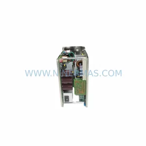
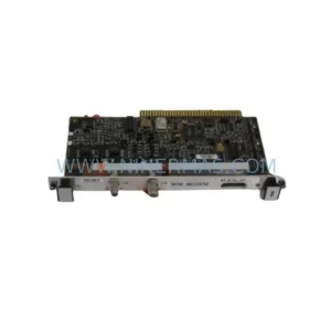
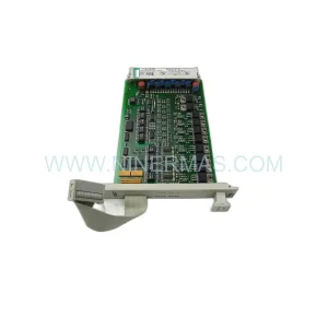
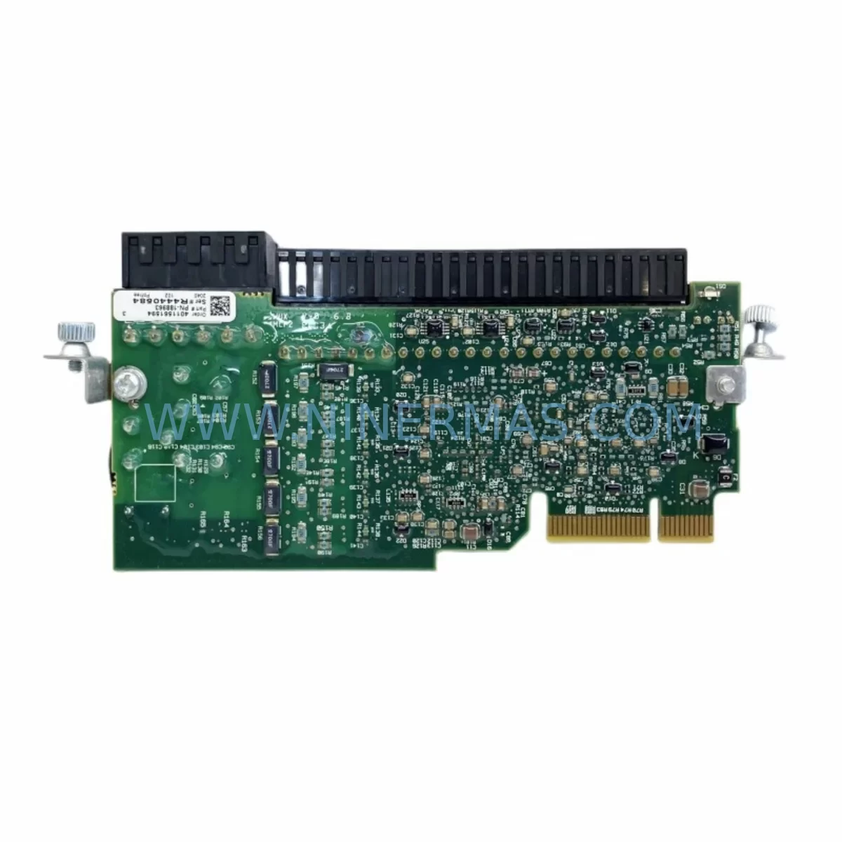
Allen-Bradley 20-750-S Safe Torque Off for PowerFlex 750
Verify the part, confirm the platform family, and move straight into quotation with the right commercial details.
RFQ Ready
- SKU20-750-S
- CategorySIS Safety & Redundancy Systems
- BrandAllen-Bradley
- SupportAvailability, lead time, condition, and shipping coordination
How Buyers Usually Use This Page
- Confirm the exact part number and platform family before sending the quote request.
- Use direct email when quantity, condition, and destination are already defined internally.
- Switch to the broader brand or category archive when you need alternates nearby.
Series Navigation
Move through the most common platform families behind this part.
Product RFQ
Send this part directly for quotation.
Include quantity, required condition, destination country, and target delivery timing. Current reference: Allen-Bradley 20-750-S Safe Torque Off for PowerFlex 750 with SKU 20-750-S.
Allen-Bradley 20-750-S Safe Torque Off Module: Retrofit-Compatible Upgrade for Legacy PowerFlex 750 Systems
The Allen-Bradley 20-750-S Safe Torque Off (STO) Module is a dedicated safety option card engineered for the PowerFlex 750 Series AC drive platform. Designed to meet IEC 61508 SIL 2 and EN ISO 13849-1 PLd safety integrity requirements, this module provides a hardware-level torque inhibit function without the need to remove power from the entire drive. For facilities operating aging PowerFlex 700 or PowerFlex 40 installations — or those migrating from third-party drive platforms — the 20-750-S represents a critical upgrade path that preserves existing control cabinet architecture while bringing safety compliance up to current standards.
When planning a retrofit around the 20-750-S, engineers must first audit the host drive’s option card bay configuration. The PowerFlex 750 Series supports up to five peripheral option slots (Ports 1–5), and the 20-750-S must be seated in Port 4 or Port 5 to function correctly as a safety-rated peripheral. Installers migrating from a legacy PowerFlex 700 drive — which used a different option card form factor and did not natively support STO — will need to verify that the replacement PowerFlex 755 or PowerFlex 753 frame size matches the existing panel cutout and DIN rail footprint. In many retrofit scenarios, the 20-COMM-E2P EtherNet/IP dual-port communication adapter or the 20-750-DNET DeviceNet adapter is already installed in Port 1, and the STO module must be added without disturbing the existing communication stack.
Terminal wiring for the 20-750-S follows a two-channel STO input architecture. Channels 1 and 2 must be wired independently from the safety relay or safety PLC output — typically a GuardLogix 5580 or a Compact GuardLogix 5380 controller — to the STO input terminals on the module’s 4-pin connector. Engineers replacing an older emergency-stop relay circuit should confirm that the safety relay output voltage (24 VDC nominal) matches the STO input specification and that cable routing maintains separation from high-voltage conductors within the control cabinet. Where the original installation used a simple hardwired E-stop loop without category-rated monitoring, upgrading to the 20-750-S with a proper safety relay such as the MSR127RP or integrating directly into a GuardLogix safety task provides a documented, auditable SIL 2 safety function.
Upgrade Compatibility Table
| Parameter | Details |
|---|---|
| Compatible Drive Platform | PowerFlex 750 Series (PowerFlex 753, PowerFlex 755, PowerFlex 755T) |
| Option Card Port Requirement | Port 4 or Port 5 only |
| STO Input Voltage | 24 VDC (dual-channel, sourcing) |
| Safety Rating | SIL 2 (IEC 61508), PLd Cat. 3 (EN ISO 13849-1) |
| Communication Compatibility | Compatible with 20-COMM-E2P (EtherNet/IP), 20-750-DNET (DeviceNet), 20-750-PROFIBUS (PROFIBUS DP) |
| Replaces / Upgrades From | Legacy PowerFlex 700 (no native STO), PowerFlex 40 (no STO option), third-party drives with hardwired E-stop only |
| Backplane Interface | PowerFlex 750 Series peripheral option card edge connector |
| Installation Space | Single option card slot; no additional panel space required |
| Commissioning Tool | Studio 5000 Logix Designer v21 or later; DriveExplorer or DriveExecutive for parameter verification |
| Retrofit Wiring Adapter | No adapter required; direct terminal block connection |
| Warranty | 12 Months — covers manufacturing defects, functional failure under normal operating conditions |
Retrofit Planning for Existing Automation Systems
A successful 20-750-S retrofit begins well before the maintenance window opens. The first step is a full parameter backup of the existing drive using DriveExecutive or the Studio 5000 Drive Configuration tool. All parameter sets — including speed references, accel/decel ramps, current limits, and any application-specific logic blocks stored in the 20-750-ENETR or 20-COMM-E2P adapter — must be exported and archived. If the existing installation includes a 20-750-UFB universal feedback option card for encoder or resolver feedback, its configuration must also be documented, as the STO module installation may require a port reassignment.
For lines running a Logix-based control architecture, the GuardLogix safety task must be updated to include the STO function block and the associated safety I/O mapping. Engineers should verify that the 1756-IB16S or 1791DS-IB12 safety input module wired to the E-stop circuit is correctly mapped in the safety task before the 20-750-S is commissioned. Where the control system uses a ControlLogix 5580 or CompactLogix 5380 standard (non-safety) controller, a dedicated safety relay must be interposed between the controller output and the STO input terminals — the 20-750-S does not accept standard (non-safety-rated) digital outputs as a compliant STO activation source.
Panel builders retrofitting multiple drives in a single cabinet should plan the STO wiring loop carefully. Each 20-750-S module requires its own independent dual-channel STO connection; daisy-chaining STO inputs across multiple drives is not permitted under SIL 2 architecture. Where cabinet space is constrained, the 20-750-2 (two-channel STO with feedback monitoring) may be evaluated as an alternative, though the 20-750-S remains the standard replacement for most PowerFlex 753 and PowerFlex 755 installations. Signal isolators such as the 1492-IFM20F may be required where long cable runs between the safety relay and the drive introduce noise or voltage drop concerns.
HMI integration should also be reviewed during the retrofit planning phase. If the existing HMI — whether a PanelView Plus 7 or a PanelView 800 — displays drive status tags sourced from the 20-COMM-E2P adapter, the addition of the 20-750-S will introduce new STO status bits (STO Active, STO Fault, Channel 1/2 Status) that should be mapped to the HMI display for operator visibility. Failing to update the HMI screen can result in operators being unaware of an active STO condition, which may cause unnecessary downtime or unsafe restart attempts.
Downtime Control During System Migration
Minimizing production downtime during a 20-750-S installation requires a structured pre-outage preparation protocol. All parameter files, safety task exports, and HMI screen backups should be completed and verified during normal production hours — before the maintenance window begins. A bench-tested spare drive with the 20-750-S pre-installed and pre-configured is the most effective way to reduce in-cabinet installation time to a simple swap, re-termination, and functional test sequence.
During the outage, the sequence should follow: (1) isolate and lock out the drive per LOTO procedures; (2) remove the existing option cards in reverse port order, noting cable routing; (3) seat the 20-750-S in Port 4 or Port 5 and secure the retention latch; (4) reconnect STO wiring to the dual-channel terminal block; (5) restore power and verify STO status via the drive’s HIM (Human Interface Module) or via Studio 5000 online monitoring. The STO function should be validated by deliberately opening the STO input circuit and confirming that the drive enters the STO state without faulting the safety task — a critical distinction that confirms correct wiring polarity and channel integrity.
Where the original program logic used a timed restart sequence after an E-stop event, the safety task must be reviewed to ensure that the STO reset logic requires a deliberate operator action (manual reset) rather than an automatic restart. This is both a safety requirement under IEC 62061 and a common audit finding during post-retrofit safety validation. Documenting the commissioning test results — including STO response time measurements and channel diagnostic coverage — provides the evidence package required for CE marking or OSHA compliance reviews.
Retrofit Support FAQ
Q1: Can the 20-750-S directly replace the hardwired E-stop relay circuit in my existing PowerFlex 700 installation?
The 20-750-S is designed for the PowerFlex 750 Series platform and cannot be installed in a PowerFlex 700 drive. A full drive replacement to a PowerFlex 753 or PowerFlex 755 is required. Once the new drive is installed, the 20-750-S provides a certified STO function that replaces the legacy hardwired E-stop relay, provided the safety relay or GuardLogix output is correctly wired to the dual-channel STO input terminals.
Q2: What commissioning tests are required after installing the 20-750-S?
At minimum, a functional STO validation test must be performed: with the drive running at low speed under no-load conditions, open the STO input circuit and confirm the drive enters the STO state (motor coasts to stop, drive does not fault). Both channels must be tested independently to verify dual-channel integrity. Results should be recorded in the machine’s safety validation report. NINERMAS supplies units that have passed pre-shipment functional testing; commissioning test documentation is available upon request.
Q3: Is the 20-750-S compatible with PROFIBUS DP or DeviceNet communication networks?
Yes. The 20-750-S occupies a dedicated option port and does not conflict with communication adapters installed in other ports. It is fully compatible with installations using the 20-750-PROFIBUS PROFIBUS DP adapter or the 20-750-DNET DeviceNet adapter. STO status information is accessible via the drive’s parameter table and can be mapped to the communication adapter’s I/O assembly for PLC monitoring.
Q4: What does the 12-month warranty cover, and what is the supply lead time?
NINERMAS provides a 12-month warranty on the 20-750-S covering manufacturing defects and functional failure under normal operating conditions. Units are sourced from verified supply channels and undergo pre-shipment inspection. Stock availability is maintained for immediate dispatch; lead time for in-stock units is typically 3–7 business days depending on destination. For urgent retrofit requirements or bulk procurement, contact our sales team directly for priority allocation and expedited shipping options.
| Product Series | powerflex |
|---|---|
| Country of Origin | US |
Catalog Continuation
More Allen-Bradley modules in the catalog.
Use the brand lane to compare nearby part numbers, platform-adjacent modules, and other inquiry-ready listings before sending your final RFQ.
Catalog Continuation
Alternative parts within SIS Safety & Redundancy Systems.
Stay inside the same system family when you need substitutes, adjacent modules, or a broader shortlist for procurement review.
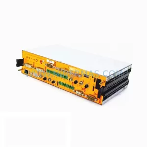
SKU: 60S-04/08-54-B-001-VC-AE-00
BAUMULLER 60S-04/08-54-B-001-VC-AE-00 Safety-Reliable Servo Drive
SKU: VE3008 KJ2005X1-MQ2 13P0072X082
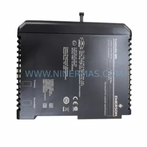
Emerson VE3008 KJ2005X1-MQ2 Safety-Reliable I/O for Critical Control Sites