Original Industrial Spare Part
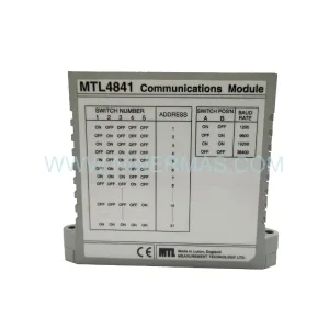
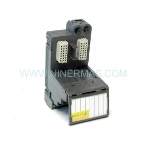
Q-SWITCH 120065-002 Retrofit-Compatible Switch Module
Verify the part, confirm the platform family, and move straight into quotation with the right commercial details.
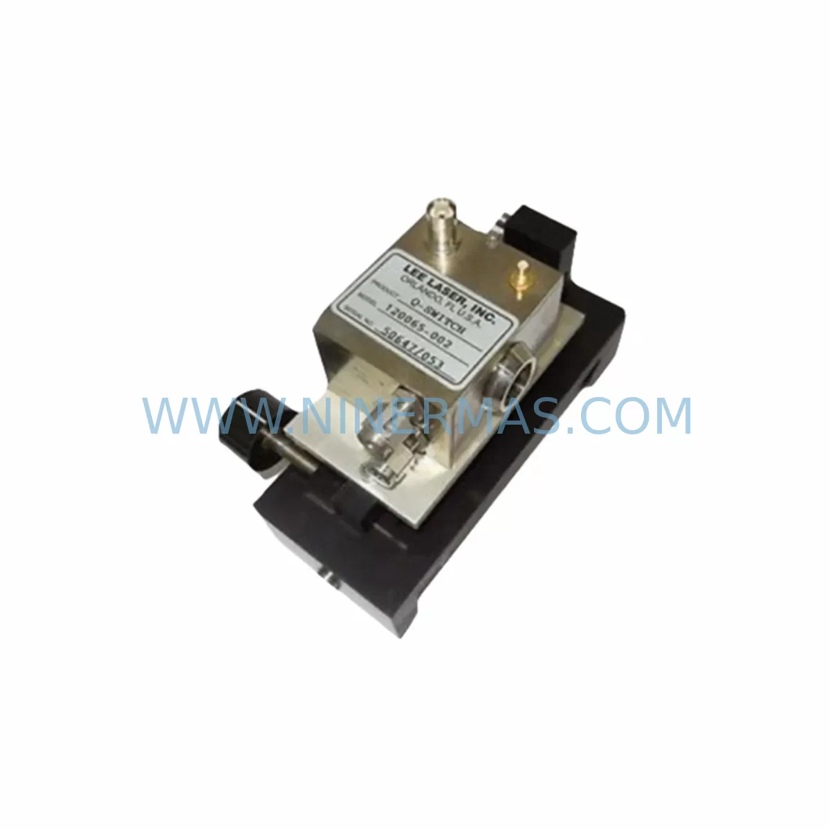
RFQ Ready
- SKU120065-002
- CategoryPLC & Industrial Automation Modules
- BrandQ-SWITCH
- SupportAvailability, lead time, condition, and shipping coordination
How Buyers Usually Use This Page
- Confirm the exact part number and platform family before sending the quote request.
- Use direct email when quantity, condition, and destination are already defined internally.
- Switch to the broader brand or category archive when you need alternates nearby.
Series Navigation
Move through the most common platform families behind this part.
Product RFQ
Send this part directly for quotation.
Include quantity, required condition, destination country, and target delivery timing. Current reference: Q-SWITCH 120065-002 Retrofit-Compatible Switch Module with SKU 120065-002.
Q-SWITCH 120065-002 Retrofit-Compatible Switch Module: Seamless Legacy System Upgrade
The Q-SWITCH 120065-002 is a ruggedized industrial switch module engineered for demanding harsh-environment applications and purpose-built to support legacy automation system retrofit projects. As aging control panels reach end-of-life and OEM spare parts become increasingly scarce, the 120065-002 provides a verified drop-in replacement path that preserves existing wiring topology, minimizes re-engineering effort, and dramatically reduces planned downtime during system migration. Whether you are upgrading a legacy distributed control system (DCS), modernizing a programmable logic controller (PLC) rack, or restoring a discontinued safety interlock circuit, the Q-SWITCH 120065-002 delivers the electrical and mechanical compatibility your team needs to keep production running.
Upgrade Compatibility Table
| Parameter | Details / Retrofit Notes |
|---|---|
| SKU / Part Number | Q-SWITCH 120065-002 |
| Module Type | Ruggedized Industrial Switch Module |
| Mounting Interface | DIN-rail and panel-mount compatible; verify backplane slot pitch against existing rack before installation |
| Terminal / Wiring | Screw-terminal block; confirm conductor gauge and torque spec match legacy field wiring (typically 0.5–2.5 mm²) |
| Communication Compatibility | Passive switching function; no protocol dependency — compatible across Modbus RTU, PROFIBUS DP, DeviceNet, and hardwired I/O architectures |
| Power Supply Requirement | Confirm cabinet 24 VDC rail capacity before adding module; cross-reference with existing Q-SWITCH or third-party power supply unit load budget |
| Installation Space | Measure available DIN-rail length and cabinet depth; ruggedized housing may have slightly larger footprint than legacy slim-line modules |
| Replacement Recommendation | Direct replacement for discontinued 120065-001 and compatible with 120065-series switch families; verify revision suffix before ordering |
| Commissioning Focus | Verify contact state (NO/NC), actuator travel, and interlock logic in PLC ladder program before energizing; test with simulation mode where available |
| Warranty | 12-Month Warranty — covers manufacturing defects under normal industrial operating conditions |
Retrofit Planning for Existing Automation Systems
Successful integration of the Q-SWITCH 120065-002 into an existing automation environment begins with a thorough pre-retrofit audit. Before removing the legacy switch module, document the current terminal wiring diagram, photograph all field connections, and record the module address assignment within the PLC I/O map. If the control system uses a modular rack architecture — such as a multi-slot backplane shared with analog input cards, digital output modules, or communication interface modules — confirm that removing the old switch module does not interrupt the backplane power bus or disrupt adjacent slot addressing.
Power budget verification is a critical step that is frequently overlooked. The 24 VDC distribution rail inside the control cabinet must have sufficient headroom to support the 120065-002 alongside co-installed components such as signal isolators, relay output modules, and 24 VDC-powered communication gateways. If the existing Q-SWITCH power supply unit is already operating near rated capacity, consider adding a supplementary DIN-rail power supply before proceeding with the swap.
Terminal block compatibility deserves careful attention. Legacy panels built more than ten years ago may use older screw-terminal formats with non-standard conductor entry angles. The 120065-002 uses a standard screw-terminal block, but field wiring ferrules should be inspected and replaced if corroded or undersized. Where the original installation used push-in spring terminals on a competing brand’s I/O module, a short adapter harness may be required to bridge the wiring to the 120065-002’s screw terminals without disturbing the rest of the cabinet wiring.
For systems that include an HMI panel — whether a legacy operator terminal running proprietary graphics or a modern touchscreen HMI communicating over Ethernet/IP — the switch module replacement should be coordinated with a review of the HMI tag database. If the 120065-002 replaces a module whose I/O address has changed due to rack re-configuration, the corresponding HMI screen objects and alarm setpoints must be updated to reflect the new address mapping before the system is returned to service.
Communication link integrity must be validated end-to-end after installation. In PROFIBUS DP networks, adding or removing a node changes the bus termination balance; confirm that the DP master still polls all slave addresses correctly after the retrofit. In Modbus RTU architectures, verify that the baud rate, parity, and stop-bit settings on the new module match the master controller configuration. Where the legacy system used a dedicated programming cable or serial adapter for field diagnostics, ensure that the same interface remains accessible after the 120065-002 is installed in the cabinet.
I/O expansion considerations are equally important. If the retrofit is part of a broader system upgrade that adds new sensor inputs or actuator outputs, plan the I/O module count and rack slot allocation before finalizing the cabinet layout. Adding digital input modules, analog output cards, or safety relay modules to the same rack as the 120065-002 requires careful slot assignment to avoid address conflicts in the PLC program. Where the existing rack is fully populated, a secondary expansion rack connected via a rack extension cable may be necessary.
Finally, confirm installation space with physical measurements before ordering. The ruggedized housing of the 120065-002 is designed for harsh environments — vibration, dust, and wide temperature ranges — but its physical dimensions may differ slightly from the slim-line legacy module it replaces. Allow adequate clearance for cable routing, terminal access, and heat dissipation within the control cabinet.
Downtime Control During System Migration
Minimizing unplanned downtime is the primary concern for any maintenance team executing a switch module replacement on a live production line. The recommended approach for the Q-SWITCH 120065-002 retrofit is a structured hot-swap preparation protocol: pre-stage the replacement module on the bench, verify its contact configuration and actuator function before entering the cabinet, and prepare a rollback plan in case the first installation attempt reveals an unexpected wiring incompatibility.
Where the control system architecture permits, use the PLC’s force-output capability to hold the affected I/O channel in a safe state while the physical module swap is performed. This technique preserves the continuity of the control program logic and prevents nuisance trips on downstream safety interlocks or process alarms. After the 120065-002 is seated and wired, release the forced output and observe the channel state in the PLC monitoring software before closing the cabinet door.
Protecting the original program logic is non-negotiable. Before any hardware change, upload and archive the current PLC program — including all data blocks, function blocks, and HMI tag exports — to a secure backup location. If the retrofit involves a controller platform migration (for example, moving from a legacy fixed-format PLC to a modular rack-based system), engage the OEM’s migration tool or a qualified system integrator to perform a program conversion audit. The 120065-002’s passive switching function means that its integration into the new program is straightforward, but the surrounding I/O addressing and interlock logic must be verified in simulation before live commissioning.
Field commissioning should follow a structured test sequence: energize the module, verify the contact state against the PLC input status display, actuate the switch manually and confirm the PLC registers the state change, then run the full interlock test sequence as defined in the site’s functional safety test procedure. Document all test results and retain them as part of the retrofit record for future maintenance reference. With proper preparation, a Q-SWITCH 120065-002 replacement can typically be completed within a single planned maintenance window, keeping total production downtime to a minimum.
Retrofit Support FAQ
Q1: Is the Q-SWITCH 120065-002 a direct replacement for the discontinued 120065-001?
The 120065-002 is the current production revision of the 120065 switch module family and is designed as a functional replacement for the 120065-001. Verify the revision suffix on your existing module label and confirm terminal pin-out compatibility using the wiring diagram before installation. In most documented retrofit cases, the 120065-002 is a drop-in replacement with no wiring modifications required.
Q2: What commissioning steps are required after installation?
After seating the module and completing terminal wiring, perform the following: (1) verify 24 VDC supply voltage at the module terminals; (2) confirm contact state (NO or NC) matches the PLC I/O configuration; (3) actuate the switch and observe the corresponding PLC input bit in the monitoring software; (4) run the site’s interlock functional test sequence and document results. If the system includes an HMI, verify that the associated screen object reflects the correct switch state before returning the system to automatic mode.
Q3: Can the 120065-002 be used in PROFIBUS DP or Modbus RTU networks?
The Q-SWITCH 120065-002 is a hardwired switch module and does not itself participate in fieldbus communication. It connects to the digital input channel of a PLC or DCS I/O module, which in turn communicates over PROFIBUS DP, Modbus RTU, DeviceNet, or any other supported protocol. This architecture means the 120065-002 is protocol-agnostic and compatible with any control platform that accepts a standard dry-contact or 24 VDC digital input signal.
Q4: What does the 12-month warranty cover, and is in-stock supply guaranteed?
The Q-SWITCH 120065-002 carries a 12-month warranty covering manufacturing defects under normal industrial operating conditions. Warranty claims require the original purchase documentation and a description of the failure mode. Regarding supply: NINERMAS maintains dedicated stock of the 120065-002 as part of its spare-parts lifecycle program, supporting long-term procurement planning for customers with multi-year maintenance contracts. Contact our team to confirm current inventory levels and lead times for your project.
| Product Series | Other series |
|---|
Catalog Continuation
Alternative parts within PLC & Industrial Automation Modules.
Stay inside the same system family when you need substitutes, adjacent modules, or a broader shortlist for procurement review.
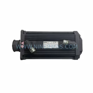
SKU: 14L41-RS0B0-B24R-ST5S00N-R0SU
LENZE 14L41-RS0B0-B24R-ST5S00N-R0SU Retrofit for Legacy Systems
SKU: CI540 3BSE001077R1
ABB CI540 3BSE001077R1 Spare Part for Industrial Maintenance
SKU: ZINT-541 3AUA00000658960
ABB ZINT-541 3AUA00000658960 Retrofit-Compatible Inverter Power Module