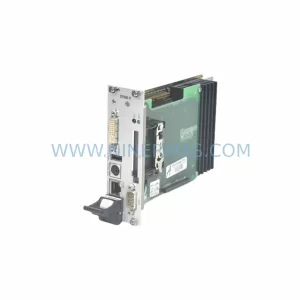
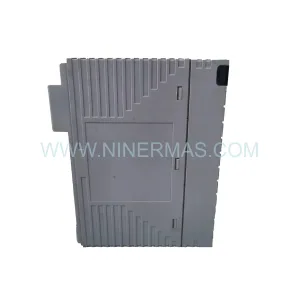
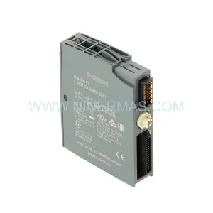
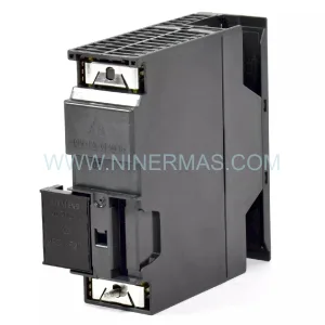
Original Industrial Spare Part
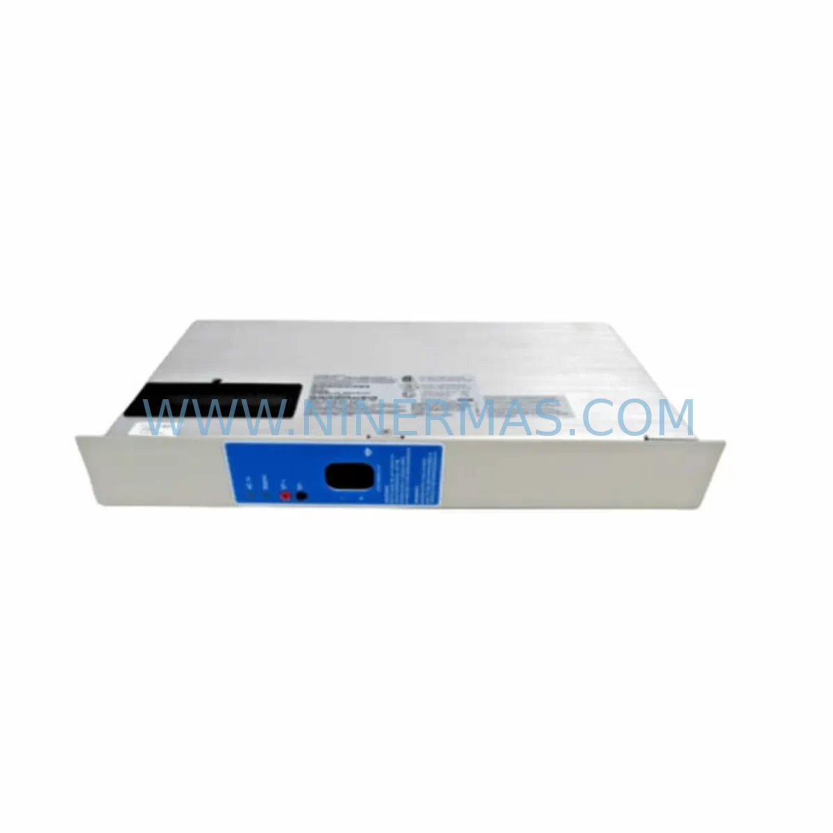
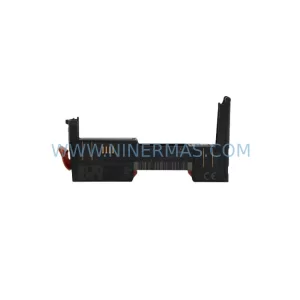
B&R X67DO1332 Retrofit-Compatible Digital Output Module
Verify the part, confirm the platform family, and move straight into quotation with the right commercial details.
RFQ Ready
- SKUX67DO1332
- CategoryPLC & Industrial Automation Modules
- BrandB&R
- SupportAvailability, lead time, condition, and shipping coordination
How Buyers Usually Use This Page
- Confirm the exact part number and platform family before sending the quote request.
- Use direct email when quantity, condition, and destination are already defined internally.
- Switch to the broader brand or category archive when you need alternates nearby.
Series Navigation
Move through the most common platform families behind this part.
Product RFQ
Send this part directly for quotation.
Include quantity, required condition, destination country, and target delivery timing. Current reference: B&R X67DO1332 Retrofit-Compatible Digital Output Module with SKU X67DO1332.
B&R X67DO1332 Retrofit-Compatible Digital Output Module for Legacy Systems
The B&R X67DO1332 is a ruggedized, IP67-rated digital output module from B&R’s X67 field bus system series, engineered for decentralized I/O deployment in harsh industrial environments. Designed to operate without a control cabinet, the X67DO1332 delivers 12 digital outputs with 24 VDC switching capability, making it a critical component in legacy automation retrofits, discontinued spare part replacements, and control system modernization projects across manufacturing, automotive, food & beverage, and heavy industry sectors.
For engineers managing aging B&R automation platforms, the X67DO1332 represents a direct-fit solution for extending the operational life of existing X67 field networks. Whether you are replacing a failed output module on a legacy production line, upgrading a distributed I/O architecture, or migrating from an older POWERLINK generation to a current B&R Automation Studio-compatible topology, the X67DO1332 integrates without requiring structural changes to the existing field wiring or module addressing scheme.
Upgrade Compatibility Table
| Parameter | X67DO1332 Specification | Retrofit / Replacement Notes |
|---|---|---|
| Output Channels | 12 × Digital Output, 24 VDC | Verify channel count matches legacy module; bridge unused terminals if replacing 8-channel predecessors |
| Protection Rating | IP67 (dust-tight, immersion-resistant) | Suitable for direct field mounting; no cabinet enclosure required |
| Communication Interface | X2X Link / POWERLINK | Compatible with B&R X20 CPU modules and X67 bus controllers; confirm firmware version on X67BC0083 or X67BC1321 bus controller |
| Supply Voltage | 24 VDC (module and field power) | Confirm existing power supply capacity; X67PS1300 or equivalent field power supply recommended for multi-module segments |
| Connector Type | M12 connectors (A-coded) | Existing M12 field cables are reusable; inspect for pin corrosion on legacy harnesses |
| Module Addressing | Automatic via X2X Link topology | Slot position determines logical address; no manual DIP switch setting required |
| Automation Studio Compatibility | AS 3.x / 4.x | Import existing hardware configuration; re-map I/O variables if upgrading from AS 2.x projects |
| Installation Footprint | Standard X67 module form factor | Direct mechanical replacement for X67DO1321, X67DO1322 in same mounting rail segment |
| Warranty | 12-Month Warranty — all units ship tested and verified | |
Retrofit Planning for Existing Automation Systems
Successful integration of the X67DO1332 into a legacy automation environment requires a structured pre-installation assessment. Begin by auditing the existing X67 field segment: document the current module sequence, confirm the bus controller model (typically an X67BC0083 or X67BC1321), and verify that the installed Automation Studio project version supports the X67DO1332 hardware description file (HDF). If the project was originally developed under an older AS release, the HDF import process must be completed before the hardware configuration can be compiled and downloaded.
Power budget verification is a non-negotiable step. Each X67 segment draws field power through the bus controller or a dedicated X67PS1300 field power supply module. Adding or replacing output modules changes the total current draw on the 24 VDC field bus. Calculate the aggregate output load — particularly if the X67DO1332 is driving solenoid valves, relay coils, or indicator arrays — and confirm that the upstream power supply, whether a B&R PS3100 or a third-party 24 VDC DIN-rail unit, has sufficient headroom. A minimum 20% power margin is recommended for retrofit installations.
Terminal and connector inspection is equally critical. The X67DO1332 uses M12 A-coded connectors for both power and signal. On legacy lines where the original field cabling has been in service for five or more years, inspect each M12 connector for pin corrosion, seal degradation, and cable jacket cracking. Reusing compromised connectors is a leading cause of intermittent faults post-retrofit. Where cabling must be replaced, maintain the original wire color coding and labeling to preserve traceability against the existing electrical schematics.
For systems that also incorporate X67DI1321 digital input modules, X67AI1323 analog input modules, or X67AO1322 analog output modules in the same field segment, the retrofit sequence should address all modules in a single planned maintenance window rather than piecemeal replacements. This approach minimizes the number of Automation Studio download cycles and reduces the risk of configuration mismatches between the live PLC program and the physical hardware topology.
Where the legacy system includes an X20CP1485 or X20CP3485 controller communicating over POWERLINK to the X67 field nodes, confirm that the POWERLINK cycle time configured in the existing project is compatible with the X67DO1332’s response time specification. In high-speed motion or synchronized output applications, a cycle time mismatch can cause output jitter or watchdog faults. Review the POWERLINK network configuration in Automation Studio’s physical view and adjust the cycle time if necessary before commissioning.
HMI screen updates are frequently overlooked during output module retrofits. If the plant’s B&R Power Panel or third-party SCADA system displays output status tags mapped to the legacy module’s I/O variables, verify that the variable names and data types remain consistent after the hardware configuration update. A mismatch between the HMI tag database and the updated PLC variable table will result in incorrect status displays or alarm suppression — a safety-critical issue in process control environments.
For installations that include signal isolation requirements — for example, where the X67DO1332 drives loads in a different ground reference zone — consider adding DIN-rail signal isolators or relay output terminal blocks between the module outputs and the field devices. This is particularly relevant in retrofit scenarios where the original control cabinet design did not anticipate the IP67 field-mounted architecture of the X67 platform.
Downtime Control During System Migration
Minimizing unplanned downtime is the primary operational constraint in any legacy system retrofit. For the X67DO1332 replacement, the recommended approach is a cold-swap procedure executed during a scheduled maintenance window. Before powering down the field segment, export a full backup of the Automation Studio project — including the runtime configuration, I/O mapping, and POWERLINK network parameters — to a secure offline location. This backup serves as the recovery baseline if the commissioning process encounters unexpected faults.
During the physical swap, label each M12 connector with its corresponding terminal designation before disconnection. Photograph the existing module installation from multiple angles to document the cable routing, module orientation, and any field markings. These reference images are invaluable during reassembly, particularly in dense field junction boxes where multiple X67 modules are mounted in close proximity.
After installing the X67DO1332, power up the field segment and allow the X2X Link bus to enumerate the new module. In Automation Studio’s online mode, verify that the module appears in the correct slot position and that the I/O status indicators on the module itself show normal operation (green bus LED, no fault LED). Perform a forced output test on each of the 12 channels before releasing the line to production — this confirms both the module’s output driver integrity and the continuity of the field wiring to each connected load.
For critical production lines where even a scheduled maintenance window carries significant cost, consider staging a parallel test rack with the X67DO1332 pre-configured and validated against a copy of the production Automation Studio project. This pre-commissioning approach allows the engineering team to resolve any configuration issues offline, reducing the live installation window to a physical swap and a brief functional verification — typically achievable within 30 to 60 minutes for a single-module replacement.
All X67DO1332 units supplied by NINERMAS undergo pre-shipment functional testing, including output channel verification and bus communication validation. Each unit ships with a 12-month warranty covering manufacturing defects and premature component failure under normal operating conditions.
Retrofit Support FAQ
Q1: Is the X67DO1332 a direct replacement for the X67DO1321 or X67DO1322?
The X67DO1332 is mechanically and electrically compatible with the X67DO1321 and X67DO1322 in most retrofit scenarios. The primary difference lies in the output channel count and current rating. Confirm the channel mapping in your Automation Studio hardware configuration and update the HDF if required. No field wiring changes are typically necessary when replacing within the same X67 module family.
Q2: What commissioning steps are required after installing the X67DO1332 in a live X67 segment?
After physical installation, power up the X2X Link segment and verify module enumeration in Automation Studio online mode. Perform a forced output test on all 12 channels, confirm POWERLINK cycle time compatibility, and validate HMI tag mapping before returning the line to production. A full project backup should be completed before and after the commissioning download.
Q3: Can the X67DO1332 be used with non-B&R controllers via third-party POWERLINK masters?
The X67DO1332 communicates via B&R’s X2X Link protocol, which is proprietary to the X67 field bus system and requires a B&R X67 bus controller as the segment master. It is not directly compatible with third-party POWERLINK masters without a B&R bus controller intermediary. For mixed-vendor architectures, consult B&R’s system integration documentation or contact NINERMAS for application-specific guidance.
Q4: What is the warranty coverage and what does pre-shipment testing include?
All X67DO1332 units supplied by NINERMAS carry a 12-month warranty from the date of shipment. Pre-shipment testing includes output channel functional verification, bus communication validation, and visual inspection for mechanical damage. Units that fail any test criterion are quarantined and not shipped. Warranty claims are processed through sale@ninermas.com with a target response time of one business day.
| Product Series | Other series |
|---|---|
| Country of Origin | AT |
Catalog Continuation
More B&R modules in the catalog.
Use the brand lane to compare nearby part numbers, platform-adjacent modules, and other inquiry-ready listings before sending your final RFQ.
SKU: 8BVI0220HCD8.000-1
B&R 8BVI0220HCD8.000-1 Retrofit-Compatible Servo Drive for Legacy Systems
SKU: 5PC910.SX05-00
B&R 5PC910.SX05-00 Retrofit Industrial PC for Legacy Systems
Catalog Continuation
Alternative parts within PLC & Industrial Automation Modules.
Stay inside the same system family when you need substitutes, adjacent modules, or a broader shortlist for procurement review.