Original Industrial Spare Part
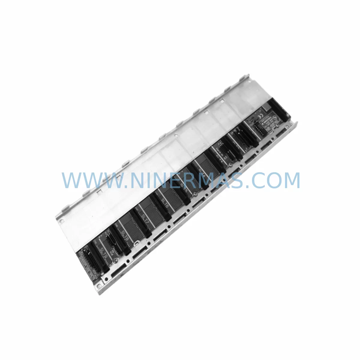
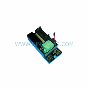
Yokogawa F3BU09-0N Service-Ready Spare Part for Industrial Maintenance
Verify the part, confirm the platform family, and move straight into quotation with the right commercial details.
RFQ Ready
- SKUF3BU09-0N
- CategoryDCS Distributed Control Systems
- BrandYokogawa
- SupportAvailability, lead time, condition, and shipping coordination
How Buyers Usually Use This Page
- Confirm the exact part number and platform family before sending the quote request.
- Use direct email when quantity, condition, and destination are already defined internally.
- Switch to the broader brand or category archive when you need alternates nearby.
Series Navigation
Move through the most common platform families behind this part.
Product RFQ
Send this part directly for quotation.
Include quantity, required condition, destination country, and target delivery timing. Current reference: Yokogawa F3BU09-0N Service-Ready Spare Part for Industrial Maintenance with SKU F3BU09-0N.
Yokogawa F3BU09-0N Service-Ready Spare Part for Industrial Maintenance
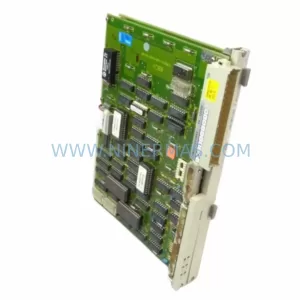
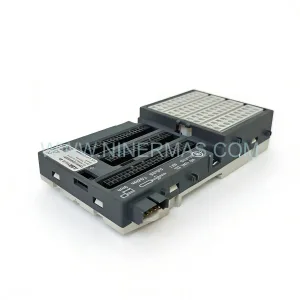
The Yokogawa F3BU09-0N is a 9-slot base unit module designed for the FA-M3 Series programmable controller platform — one of Yokogawa’s most widely deployed process and factory automation architectures. As a structural backbone of the FA-M3 control cabinet, the F3BU09-0N provides the physical mounting frame and backplane bus for CPU modules, I/O modules, power supply modules, and communication modules. When this base unit reaches end-of-life or sustains physical or electrical damage, the entire control rack becomes non-functional, making rapid spare part availability a critical factor in minimizing unplanned downtime and production loss.
At NINERMAS, we stock the F3BU09-0N as a service-ready spare part, pre-inspected and tested before shipment, backed by a 12-month warranty. Our inventory supports maintenance engineers and procurement teams managing aging FA-M3 installations across process industries, discrete manufacturing, utilities, and infrastructure projects.
Spare Maintenance Table
| Parameter | Specification |
|---|---|
| SKU / Part Number | F3BU09-0N |
| Brand | Yokogawa |
| Series | FA-M3 (STARDOM / FA-M3R compatible) |
| Module Type | 9-Slot Base Unit / Backplane |
| Compatible CPU Modules | F3SP22-0S, F3SP28-3N, F3SP38-6N, F3SP53-4H, F3SP58-6S, F3SP67-6S |
| Slot Capacity | 9 module slots (CPU + I/O + Communication) |
| Bus Interface | FA-M3 internal backplane bus |
| Power Input | Via dedicated FA-M3 power supply module (e.g. F3PU20-0S, F3PU30-0S) |
| Mounting | DIN rail or panel mount |
| Operating Temperature | 0°C to 55°C |
| Storage Temperature | -25°C to 70°C |
| Relative Humidity | 10% to 90% RH (non-condensing) |
| Origin | Japan |
| Warranty | 12 Months (NINERMAS) |
| Condition | New / Service-Ready Stock |
| Lead Time | In stock — ships within 2 business days |
| Application | Process control, factory automation, utilities, infrastructure |
| Maintenance Note | Inspect backplane connectors and slot guides before installation; verify power supply module compatibility |
Maintenance Planning for Continuous Operation
Replacing the F3BU09-0N base unit is rarely an isolated task. The base unit is the physical and electrical hub of the entire FA-M3 rack, and a thorough replacement procedure requires systematic inspection of every module and connection in the cabinet. Maintenance engineers should treat a base unit replacement as a full rack audit opportunity.
Begin with the power supply module — the F3PU20-0S or F3PU30-0S — verifying output voltage stability and checking for capacitor aging or thermal discoloration. A degraded power supply will stress the new base unit immediately after installation. Alongside the power supply, inspect the 24VDC field power rail and any associated terminal blocks for corrosion, loose wiring, or insulation breakdown.
Next, audit all I/O modules seated in the rack — digital input modules such as the F3XD32-3N, digital output modules such as the F3YD32-3N, and analog I/O modules such as the F3AD04-1N or F3DA04-1N. Backplane connector pins on aged modules can cause intermittent faults even when the base unit itself is new. Clean or replace any module with bent or oxidized connector pins.
The CPU module — whether an F3SP38-6N, F3SP53-4H, or F3SP67-6S — should be inspected for firmware version compatibility with the replacement base unit. Confirm that the CPU’s battery backup (lithium cell) is within service life to protect program retention during power cycling.
Communication modules are another critical checkpoint. If the rack hosts an F3LE01-5T Ethernet communication module or an F3LC11-1F MELSEC/FL-net module, verify that network cables, RJ45 connectors, and switch port configurations are intact. A base unit swap is an ideal moment to re-terminate any suspect Ethernet or serial connections.
For installations using F3NC96-0N pulse counter modules or F3NC32-0N high-speed counter modules, confirm that encoder wiring and shielding are undamaged, as vibration during rack disassembly can loosen fine-gauge signal wires. Similarly, inspect any signal isolators or surge protection devices on analog input channels — these components protect I/O modules from field-side transients and are often overlooked during base unit replacements.
Finally, review the rack expansion cable if the FA-M3 system uses a multi-rack configuration with an F3BU extension base. Expansion cables and their connectors are subject to mechanical fatigue and should be tested for continuity before the system is returned to service.
Stocking a complete spare kit — including the F3BU09-0N base unit, a matched power supply module, one spare CPU module, and representative I/O modules — reduces mean time to repair (MTTR) from days to hours and is strongly recommended for critical production lines.
Site Replacement Workflow
Step 1 — Pre-Shutdown Documentation: Before powering down, capture a full rack configuration photograph and export the CPU program backup via Yokogawa’s Wide Field 3 or ToolBox FA engineering software. Record all module slot positions, I/O wiring labels, and network IP addresses.
Step 2 — Safe Isolation: Isolate the control cabinet from field power and 24VDC supply. Follow site LOTO (Lockout/Tagout) procedures. Allow capacitors in the power supply module to discharge for at least 60 seconds before handling modules.
Step 3 — Module Extraction: Remove all modules from the existing F3BU09-0N in reverse slot order. Store each module in an anti-static bag. Label each module with its slot number to ensure correct reinstallation.
Step 4 — Base Unit Replacement: Remove the faulty F3BU09-0N from the DIN rail or panel mount. Install the replacement F3BU09-0N, ensuring all mounting screws are torqued to specification and the unit is properly grounded.
Step 5 — Module Reinstallation and Wiring Check: Reinstall all modules in their original slot positions. Reconnect all I/O wiring, communication cables, and power connections. Verify terminal block torque on all field wiring.
Step 6 — Power-Up and Verification: Restore power and observe all module status LEDs. Confirm CPU RUN status, I/O module READY indicators, and communication module LINK status. Reload the program backup if required and perform a functional I/O test before returning the system to automatic operation.
This structured workflow minimizes re-work risk, ensures system compatibility is maintained, and supports a controlled return-to-service that satisfies both maintenance and safety audit requirements.
Spare Parts Support FAQ
Q1: Is the F3BU09-0N compatible with all FA-M3 CPU and I/O modules?
The F3BU09-0N is designed for the standard FA-M3 Series backplane bus and is compatible with the full range of FA-M3 CPU modules (F3SP series), I/O modules (F3XD, F3YD, F3AD, F3DA series), and communication modules (F3LE, F3LC series). Always verify the module generation and firmware revision against your system’s engineering documentation before installation.
Q2: What does the 12-month warranty cover?
NINERMAS’s 12-month warranty covers manufacturing defects and functional failures under normal operating conditions. Each unit is tested before shipment. The warranty does not cover damage caused by incorrect installation, overvoltage, or environmental conditions outside the specified operating range.
Q3: Can NINERMAS support long-term or blanket purchase orders for the F3BU09-0N?
Yes. We support long-term supply agreements and blanket PO arrangements for critical spare parts including the F3BU09-0N. This is particularly valuable for customers managing multiple FA-M3 installations or planning multi-year maintenance contracts. Contact our sales team to discuss stock reservation and lead-time commitments.
Q4: How is the F3BU09-0N tested and verified before shipment?
Each unit undergoes visual inspection for physical damage, connector integrity checks, and functional verification on a compatible FA-M3 test rack. Units that do not pass all inspection criteria are quarantined and not shipped. A test report is available upon request for quality-critical procurement processes.
| Product Series | FA-M3 |
|---|---|
| Country of Origin | JP |
Catalog Continuation
More Yokogawa modules in the catalog.
Use the brand lane to compare nearby part numbers, platform-adjacent modules, and other inquiry-ready listings before sending your final RFQ.
Catalog Continuation
Alternative parts within DCS Distributed Control Systems.
Stay inside the same system family when you need substitutes, adjacent modules, or a broader shortlist for procurement review.