Original Industrial Spare Part
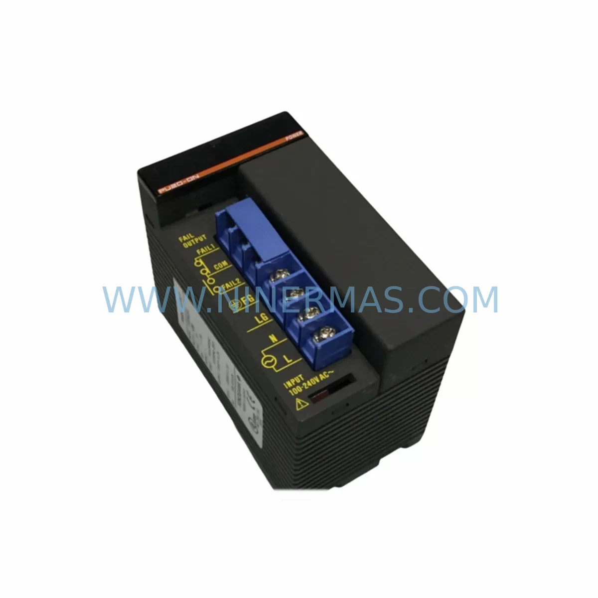
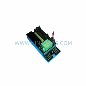
YOKOGAWA F3PU20-0N Service-Ready Spare Part for Industrial Maintenance
Verify the part, confirm the platform family, and move straight into quotation with the right commercial details.
RFQ Ready
- SKUF3PU20-ON F3PU20-0N
- CategoryDCS Distributed Control Systems
- BrandYokogawa
- SupportAvailability, lead time, condition, and shipping coordination
How Buyers Usually Use This Page
- Confirm the exact part number and platform family before sending the quote request.
- Use direct email when quantity, condition, and destination are already defined internally.
- Switch to the broader brand or category archive when you need alternates nearby.
Series Navigation
Move through the most common platform families behind this part.
Product RFQ
Send this part directly for quotation.
Include quantity, required condition, destination country, and target delivery timing. Current reference: YOKOGAWA F3PU20-0N Service-Ready Spare Part for Industrial Maintenance with SKU F3PU20-ON F3PU20-0N.
YOKOGAWA F3PU20-0N Service-Ready Spare Part for Industrial Maintenance
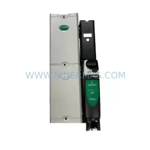
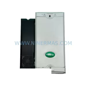
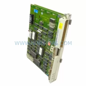
The YOKOGAWA F3PU20-0N (also referenced as F3PU20-ON) is a ruggedized DC power supply module engineered for the YOKOGAWA FA-M3 Series programmable logic controller platform — one of the most widely deployed PLC architectures in process automation, petrochemical, power generation, and discrete manufacturing environments. Designed to operate reliably under harsh industrial conditions including wide temperature ranges, high vibration, and elevated humidity, the F3PU20-0N delivers stable regulated DC power to the FA-M3 backplane and connected I/O modules, ensuring uninterrupted control system operation.
For maintenance engineers managing aging FA-M3 installations, the F3PU20-0N represents a critical line-replaceable unit (LRU). Power supply degradation is one of the leading causes of unplanned PLC downtime — capacitor aging, thermal cycling fatigue, and input voltage fluctuation all contribute to premature failure. Stocking a verified, service-ready F3PU20-0N spare eliminates the most common single point of failure in the FA-M3 power distribution chain and supports rapid recovery from unplanned outages.
Spare Maintenance Table
| Parameter | Specification / Detail |
|---|---|
| Part Number | F3PU20-0N (F3PU20-ON) |
| Brand | YOKOGAWA |
| Series | FA-M3 / F3 Series PLC |
| Module Type | Ruggedized DC Power Supply Module |
| Compatible Platform | YOKOGAWA FA-M3 PLC Backplane (F3BU□□ Series) |
| Input Voltage | 100–240 VAC, 50/60 Hz (nominal) |
| Output Voltage | Regulated DC (backplane bus voltage) |
| Operating Temperature | 0°C to +55°C (ruggedized rating) |
| Humidity | 10–90% RH, non-condensing |
| Mounting | FA-M3 base unit slot (left-side power slot) |
| Origin | Japan |
| Condition | Original / Service-Ready Spare |
| Compatibility | FA-M3 F3BU04-0N, F3BU08-0N, F3BU16-0N base units |
| Maintenance Recommendation | Inspect every 12 months; replace at first sign of output ripple or thermal alarm |
| Warranty | 12 Months — NINERMAS Quality Assurance |
| Pre-shipment Testing | Power-on functional test, output voltage verification |
Maintenance Planning for Continuous Operation
When a maintenance or procurement engineer schedules replacement of the F3PU20-0N, best practice demands a systematic review of all interdependent components within the same FA-M3 control cabinet. The power supply module does not operate in isolation — its output directly feeds every module installed on the backplane, and a degraded supply can cause cascading faults across the entire rack before a hard failure is detected.
Begin with the FA-M3 backplane unit (e.g., F3BU08-0N or F3BU16-0N): inspect the backplane bus connectors for oxidation or mechanical damage, as a compromised backplane will stress any replacement power supply. Next, audit the CPU module (such as the F3SP28-3N, F3SP38-6N, or F3SP66-4S) — firmware version compatibility and battery backup status should be confirmed before power cycling the rack during a swap.
On the I/O side, review all installed digital input modules (F3XD□□ series) and digital output modules (F3YD□□ / F3YT□□ series) for signs of contact wear or field wiring insulation breakdown. Analog I/O modules such as the F3AD04-0N (analog input) and F3DA04-0N (analog output) are particularly sensitive to power supply ripple — any instability in the F3PU20-0N output can introduce measurement drift that is difficult to diagnose without a known-good power reference.
Communication infrastructure should also be inspected during the same maintenance window. If the cabinet includes an F3LC11-1F Ethernet communication module or an F3LP02-0N PROFIBUS-DP module, verify that network link status is stable before and after the power supply replacement. Communication module resets caused by power transients during module swap are a common source of post-maintenance alarms.
For cabinets with relay output modules (F3YR□□ series), check relay contact life counters if available, and inspect terminal blocks and DIN-rail mounted terminal strips for loose connections — vibration-induced loosening is frequently discovered during power supply replacement work. Additionally, confirm that any installed signal isolators or loop-powered transmitter barriers in the same cabinet are within their rated service life, as these components share the same power distribution environment.
Finally, verify that the 24 VDC field power supply feeding sensors and actuators (often a separate YOKOGAWA or third-party DIN-rail PSU) is within specification. A failing field power supply is frequently misdiagnosed as a PLC power supply fault, and replacing the F3PU20-0N without checking the field supply can result in repeat call-outs.
Site Replacement Workflow
Step 1 — Pre-replacement documentation: Record all current I/O status, CPU program checksum, and communication link states. Photograph the existing module label to confirm the exact variant (F3PU20-0N vs. F3PU20-1N if applicable) before ordering.
Step 2 — Safe isolation: Follow site LOTO (Lockout/Tagout) procedures. The FA-M3 power supply slot is hot-swap capable on some configurations, but ruggedized variants should be replaced with the base unit de-energized to avoid transient damage to CPU and I/O modules.
Step 3 — Module extraction and inspection: Remove the F3PU20-0N by releasing the front-panel locking lever. Inspect the backplane connector pins for damage. Clean the slot with dry compressed air if contamination is present.
Step 4 — Replacement installation: Insert the service-ready F3PU20-0N spare, ensuring the module seats fully and the locking lever engages. Re-energize the base unit and confirm the POWER LED illuminates green within 3 seconds.
Step 5 — Post-replacement verification: Confirm CPU RUN status, verify all I/O module status LEDs, and check communication link restoration. Log the replacement date, module serial number, and technician ID in the site maintenance record. This documentation supports warranty claims and future lifecycle planning.
Sourcing the F3PU20-0N from NINERMAS ensures you receive a pre-tested, original spare with a 12-month warranty, reducing procurement risk for critical infrastructure maintenance. Long-term supply agreements are available for facilities managing multiple FA-M3 installations across sites.
Spare Parts Support FAQ
Q1: Is the YOKOGAWA F3PU20-0N compatible with all FA-M3 base units?
The F3PU20-0N is designed for the YOKOGAWA FA-M3 platform and is compatible with standard FA-M3 base units including the F3BU04-0N, F3BU08-0N, and F3BU16-0N. Always verify the base unit model and power slot specification against the FA-M3 hardware manual before installation. If your installation uses an extended or high-density base unit, contact our technical team to confirm compatibility.
Q2: What pre-shipment testing does NINERMAS perform on the F3PU20-0N?
Every F3PU20-0N unit shipped by NINERMAS undergoes a power-on functional test and output voltage verification prior to dispatch. Units that fail to meet original YOKOGAWA output specifications are quarantined and not shipped. A test record is available upon request for quality-critical procurement processes.
Q3: How should the F3PU20-0N be stored as a long-term inventory spare?
Store in original anti-static packaging in a dry, temperature-controlled environment (10–30°C, <70% RH). Avoid storage near strong magnetic fields or corrosive atmospheres. Inspect the spare annually and rotate stock on a first-in, first-out basis. NINERMAS recommends a maximum on-shelf storage period of 3 years before re-verification testing.
Q4: What is covered under the 12-month warranty, and how is a claim initiated?
The NINERMAS 12-month warranty covers manufacturing defects and functional failures under normal operating conditions. Physical damage caused by incorrect installation, overvoltage events, or environmental exposure beyond rated limits is excluded. To initiate a warranty claim, contact sale@ninermas.com with the order reference, installation date, and a description of the fault. Replacement or repair will be arranged within the warranty period at no additional cost.
| Product Series | FA-M3 |
|---|---|
| Country of Origin | JP |
Catalog Continuation
More Yokogawa modules in the catalog.
Use the brand lane to compare nearby part numbers, platform-adjacent modules, and other inquiry-ready listings before sending your final RFQ.
Catalog Continuation
Alternative parts within DCS Distributed Control Systems.
Stay inside the same system family when you need substitutes, adjacent modules, or a broader shortlist for procurement review.