Original Industrial Spare Part
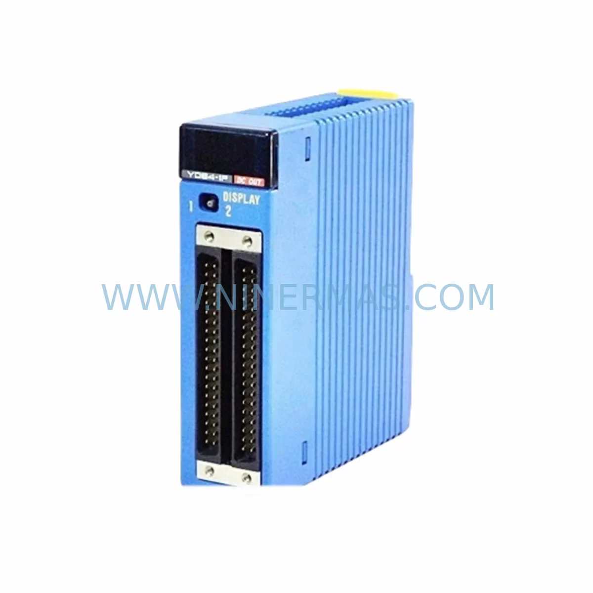
Yokogawa F3YD64-1P Retrofit-Compatible Digital Output for Legacy
Verify the part, confirm the platform family, and move straight into quotation with the right commercial details.
RFQ Ready
- SKUF3YD64-1P
- CategoryDCS Distributed Control Systems
- BrandYokogawa
- SupportAvailability, lead time, condition, and shipping coordination
How Buyers Usually Use This Page
- Confirm the exact part number and platform family before sending the quote request.
- Use direct email when quantity, condition, and destination are already defined internally.
- Switch to the broader brand or category archive when you need alternates nearby.
Series Navigation
Move through the most common platform families behind this part.
Product RFQ
Send this part directly for quotation.
Include quantity, required condition, destination country, and target delivery timing. Current reference: Yokogawa F3YD64-1P Retrofit-Compatible Digital Output for Legacy with SKU F3YD64-1P.
Yokogawa F3YD64-1P Retrofit-Compatible Digital Output for Legacy Systems
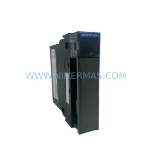
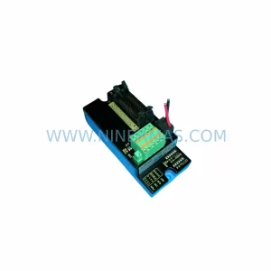
The Yokogawa F3YD64-1P is a 64-point transistor digital output module designed for the FA-M3 series programmable controller platform. As industrial facilities face the challenge of maintaining aging automation infrastructure, the F3YD64-1P has become a critical component in legacy system retrofit projects, discontinued spare parts replacement programs, and control cabinet modernization initiatives. Whether you are upgrading an end-of-life production line, restoring a decommissioned control system, or extending the operational life of an existing FA-M3 installation, the F3YD64-1P provides a direct-fit, retrofit-compatible solution that minimizes engineering rework and reduces total downtime exposure.
Sourced from verified original Yokogawa manufacturing channels, each F3YD64-1P unit supplied by NINERMAS undergoes pre-shipment functional verification to confirm output channel integrity, terminal block continuity, and backplane interface alignment. Our inventory is maintained to support urgent replacement orders, planned maintenance windows, and long-term spare parts lifecycle programs. All units are covered by a 12-month warranty from the date of shipment.
Upgrade Compatibility Table
| Parameter | F3YD64-1P Specification | Retrofit / Replacement Notes |
|---|---|---|
| Output Points | 64-point transistor (NPN sink) | Verify field device polarity before wiring; confirm NPN compatibility with actuators |
| Rated Output Voltage | 12–24 VDC | Check existing power supply capacity; F3PU20-0S power module output must support combined load |
| Output Current per Point | 0.1 A max | Audit total load current; replace any overloaded wiring harnesses before commissioning |
| Backplane Interface | FA-M3 standard bus connector | Compatible with F3BP20-0N and F3BU13-0N baseplate/bus units; confirm slot assignment in configuration tool |
| Module Address Setting | Rotary switch on module face | Match address to original module position; update I/O map in F3PU20-0S or F3LC11-1N CPU program if relocated |
| Communication Protocol | FA-M3 internal bus | No protocol migration required for same-series replacement; verify F3NC11-0N network module settings if remote I/O is used |
| Installation Space | Single slot, FA-M3 rack | Confirm available slot in existing rack; F3BP20-0N baseplate supports up to 10 I/O modules per segment |
| Commissioning Tool | WideField3 / ToolBox | Use existing ladder program; no re-compilation required for direct slot replacement |
| Warranty | 12 months from shipment date — covers manufacturing defects and output channel failure under normal operating conditions | |
Retrofit Planning for Existing Automation Systems
Successful integration of the F3YD64-1P into a legacy automation environment requires a structured pre-installation review that addresses power capacity, terminal wiring, backplane slot allocation, module addressing, program compatibility, HMI screen mapping, communication link verification, physical installation space, and on-site commissioning procedures.
Power Capacity Verification: Before installing the F3YD64-1P, confirm that the existing F3PU20-0S power supply module can sustain the additional 64-channel output load. In systems where multiple I/O modules share a single power segment, the cumulative current draw must remain within the rated capacity of the power unit. If the existing power supply is operating near its limit, consider adding a supplementary F3PU20-0S or redistributing modules across baseplate segments using an additional F3BP20-0N baseplate.
Terminal Wiring and Field Device Compatibility: The F3YD64-1P uses a 64-point terminal block layout. When replacing an older digital output module such as the F3YD32-1P (32-point variant), field wiring must be extended and re-terminated to accommodate the expanded channel count. Verify that all field cables are rated for the operating voltage and that terminal ferrules are correctly crimped. Signal isolation requirements should be reviewed — in mixed-signal environments, an F3DA04-6R analog output module or signal isolator may be installed in adjacent slots to prevent cross-interference.
Backplane and Rack Configuration: The F3YD64-1P is compatible with the FA-M3 standard backplane, including the F3BP20-0N baseplate and the F3BU13-0N bus connection unit. When inserting the module into an existing rack, confirm that the target slot is physically clear and that the backplane connector pins are undamaged. In multi-rack configurations connected via the F3BU13-0N bus unit, verify that the rack-to-rack communication link remains intact after module insertion.
Module Address and Program Compatibility: The F3YD64-1P uses a rotary address switch to define its logical position within the FA-M3 I/O map. When replacing a failed module in the same slot, the address switch should be set to match the original module’s configuration. The existing ladder logic program stored in the F3LC11-1N CPU module does not require recompilation for a direct slot replacement. However, if the module is relocated to a different slot or rack position, the I/O address references in the program must be updated using WideField3 or ToolBox programming software before restarting the system.
HMI Screen and Communication Link Review: In systems where the FA-M3 controller communicates with an HMI panel via the F3NC11-0N Ethernet communication module or a serial link, verify that the HMI tag database correctly references the F3YD64-1P output addresses after any address changes. If the system uses a MELSEC or third-party HMI connected through a protocol converter, confirm that the output register mapping remains consistent. Analog input signals monitored via the F3AD04-6R analog input module should also be verified to ensure that process feedback loops remain correctly configured after the digital output module replacement.
Installation Space and Physical Fit: The F3YD64-1P occupies a single slot in the FA-M3 rack. In compact control cabinets where space is limited, confirm that the module can be fully seated without interference from adjacent wiring ducts or cable bundles. The F3WD64-3N digital I/O module, if installed in a neighboring slot, should be checked for clearance. Adequate ventilation around the rack must be maintained to prevent thermal buildup during continuous operation.
On-Site Commissioning: After physical installation and wiring, perform a channel-by-channel output test using the FA-M3 diagnostic tools to confirm that all 64 output points respond correctly to program commands. Verify that field actuators — including solenoid valves, relay coils, and indicator lamps — activate and deactivate as expected. Document the commissioning results and retain them as part of the maintenance record for future reference.
Downtime Control During System Migration
Minimizing production downtime during a digital output module replacement is a primary concern for maintenance teams operating continuous process lines or time-sensitive manufacturing environments. The F3YD64-1P supports a controlled replacement strategy that preserves the original program logic, maintains field control continuity, and reduces the risk of unplanned process interruptions.
The recommended approach is to prepare the replacement F3YD64-1P unit off-line before the scheduled maintenance window. Set the module address switch to match the original configuration, verify the terminal block layout against the existing wiring diagram, and confirm that the backplane connector is clean and undamaged. During the maintenance window, power down the affected rack segment, remove the failed module, insert the F3YD64-1P, and restore power. The FA-M3 CPU — typically an F3LC11-1N — will automatically recognize the replacement module at the pre-configured address and resume program execution without requiring a cold restart or program reload, provided the address and slot position are unchanged.
For systems where a hot-swap or parallel operation strategy is required, consult the FA-M3 system configuration manual to determine whether the installed CPU and backplane support online module replacement. In critical applications, maintaining a pre-configured spare F3YD64-1P unit in the control room — with address switch pre-set and terminal block pre-wired — can reduce the physical replacement time to under 15 minutes, significantly limiting the impact on production continuity.
NINERMAS maintains ready stock of the F3YD64-1P to support urgent replacement orders with short lead times. Pre-shipment functional testing is performed on every unit to reduce the risk of receiving a non-functional module during a critical maintenance event.
Retrofit Support FAQ
Q1: Is the F3YD64-1P a direct replacement for older Yokogawa FA-M3 digital output modules?
Yes. The F3YD64-1P is designed as a direct slot-compatible replacement for other 64-point digital output modules in the FA-M3 series. For systems currently using the F3YD32-1P (32-point), a wiring extension and I/O map update will be required to utilize the full 64-channel capacity. Confirm the module address setting and backplane slot position before installation.
Q2: What commissioning steps are required after installing the F3YD64-1P?
After physical installation, perform a channel-by-channel output test using the FA-M3 diagnostic utility. Verify that all 64 output points activate correctly in response to program commands. If the module address or slot position has changed from the original configuration, update the I/O address references in the ladder program using WideField3 or ToolBox before restarting the CPU. Check HMI tag mappings if the system uses an F3NC11-0N network communication module for remote monitoring.
Q3: Does NINERMAS provide pre-shipment testing and a warranty for the F3YD64-1P?
Yes. Every F3YD64-1P unit supplied by NINERMAS undergoes pre-shipment functional verification covering output channel integrity, terminal block continuity, and backplane interface alignment. All units are covered by a 12-month warranty from the date of shipment, applicable to manufacturing defects and output channel failure under normal operating conditions.
Q4: What is the typical lead time and stock availability for the F3YD64-1P?
NINERMAS maintains ready inventory of the F3YD64-1P to support both urgent replacement orders and planned maintenance programs. Lead times vary based on current stock levels and shipping destination. Contact our team directly for real-time availability confirmation and expedited shipping options for critical downtime situations.
| Product Series | FA-M3 |
|---|---|
| Country of Origin | JP |
Catalog Continuation
More Yokogawa modules in the catalog.
Use the brand lane to compare nearby part numbers, platform-adjacent modules, and other inquiry-ready listings before sending your final RFQ.
Catalog Continuation
Alternative parts within DCS Distributed Control Systems.
Stay inside the same system family when you need substitutes, adjacent modules, or a broader shortlist for procurement review.