Original Industrial Spare Part
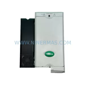
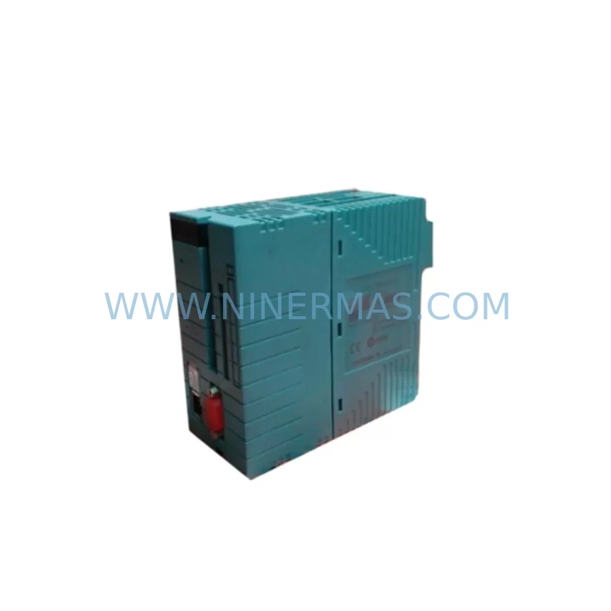
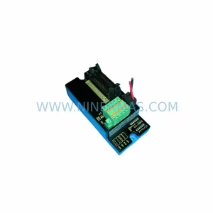
YOKOGAWA NFCP100-S00 S2 Service-Ready Spare Part
Verify the part, confirm the platform family, and move straight into quotation with the right commercial details.
RFQ Ready
- SKUNFCP100-S00 S2
- CategoryDCS Distributed Control Systems
- BrandYokogawa
- SupportAvailability, lead time, condition, and shipping coordination
How Buyers Usually Use This Page
- Confirm the exact part number and platform family before sending the quote request.
- Use direct email when quantity, condition, and destination are already defined internally.
- Switch to the broader brand or category archive when you need alternates nearby.
Series Navigation
Move through the most common platform families behind this part.
Product RFQ
Send this part directly for quotation.
Include quantity, required condition, destination country, and target delivery timing. Current reference: YOKOGAWA NFCP100-S00 S2 Service-Ready Spare Part with SKU NFCP100-S00 S2.
YOKOGAWA NFCP100-S00 S2 Service-Ready Spare Part for Industrial Maintenance
The YOKOGAWA NFCP100-S00 S2 is a critical CPU module designed for the STARDOM FCN/FCJ series distributed control system. As a service-ready spare part, it is engineered to support rapid replacement in industrial automation environments where unplanned downtime carries significant operational and financial consequences. Whether you are managing a petrochemical plant, a water treatment facility, a power generation site, or a discrete manufacturing line, maintaining a verified stock of the NFCP100-S00 S2 is a fundamental element of any responsible maintenance strategy.
For maintenance engineers and procurement specialists working with YOKOGAWA STARDOM FCN/FCJ controllers, the NFCP100-S00 S2 represents the processing core of the control node. When this module fails or degrades, the entire control loop it governs is at risk. Fault symptoms typically include unexpected controller restarts, loss of communication with the engineering station, I/O scan failures, and alarm floods that cascade across the HMI. Rapid identification and substitution of the NFCP100-S00 S2 is therefore the primary recovery action in most FCN/FCJ fault isolation procedures.
At NINERMAS, every NFCP100-S00 S2 unit is sourced, inspected, and dispatched with a 12-month warranty. Each module undergoes pre-shipment functional verification to confirm firmware compatibility, communication integrity, and hardware condition before it leaves our facility. This ensures that when your team installs the replacement on-site, the module is ready to initialize without additional conditioning or rework.
Spare Maintenance Table
| Part Number | NFCP100-S00 S2 |
| Brand | YOKOGAWA |
| Series | STARDOM FCN / FCJ |
| Module Type | CPU / Controller Module |
| Origin | Japan |
| Compatible Systems | YOKOGAWA STARDOM FCN-100, FCN-500, FCJ Series Controllers |
| Communication | Ethernet (Vnet/IP), Serial; compatible with YOKOGAWA Vnet/IP network topology |
| Power Supply Compatibility | Works with NFPS100-S00 and NFPS200-S00 power supply modules |
| Installation | Backplane-mounted; hot-swap capable in redundant configurations |
| Operating Temperature | 0°C to 55°C (standard industrial environment) |
| Humidity | 10% to 90% RH, non-condensing |
| Firmware | Compatible with STARDOM FCN/FCJ firmware revisions; confirm version with engineering station before swap |
| Maintenance Recommendation | Replace at first sign of CPU fault alarm, communication loss, or controller restart loop |
| Warranty | 12 Months from date of shipment |
| Condition | Original, tested, service-ready |
Maintenance Planning for Continuous Operation
Effective maintenance planning for a YOKOGAWA STARDOM FCN/FCJ control node extends well beyond the NFCP100-S00 S2 CPU module itself. When a maintenance engineer responds to a CPU fault or schedules a planned replacement, the surrounding components in the same control cabinet must be evaluated concurrently to prevent repeat failures and to ensure the restored system operates reliably through the next maintenance cycle.
The NFPS100-S00 and NFPS200-S00 power supply modules are the first components to inspect when replacing the NFCP100-S00 S2. A degraded power supply delivering marginal voltage can cause repeated CPU resets and may have been the root cause of the original failure. Measure output voltage under load before commissioning the replacement CPU module.
The NFIO-AIO01 and NFIO-DIO01 I/O modules mounted on the same FCN backplane should be checked for communication errors and channel faults. After a CPU replacement, I/O modules may require a re-initialization sequence to re-establish their data exchange with the new controller. Verify all analog input and digital output channels are responding correctly before returning the loop to automatic control.
The NFBU100-S00 backplane unit itself warrants inspection during any CPU swap. Backplane connector pins can oxidize or sustain mechanical damage during repeated module insertions, leading to intermittent communication faults that are difficult to diagnose after the fact. Clean and inspect the backplane connector before installing the NFCP100-S00 S2 replacement.
Communication infrastructure connected to the FCN node — including Vnet/IP Ethernet switches, patch cables, and fiber media converters — should be verified for link integrity. A CPU replacement that restores the controller but leaves a degraded network link will result in continued HMI alarms and may be misdiagnosed as a persistent CPU fault.
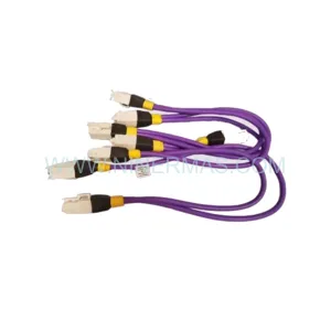
For sites running redundant FCN configurations, the NFCP100-S00 redundancy cable and the standby CPU module should both be inspected. Confirm that the redundancy switchover function is operational after the primary CPU is replaced, and that the standby module firmware version matches the primary.
Relay output modules and terminal block assemblies connected to the FCN I/O should be checked for loose wiring, corroded terminals, and blown fuses — particularly on 24VDC digital output circuits that drive solenoids, motor starters, or safety relays. These components are frequently overlooked during CPU-focused maintenance events but are common sources of post-restoration faults.
Finally, the STARDOM FCN engineering software (FAST/TOOLS or Resource Configurator) should be used to perform a full configuration download and verification after the NFCP100-S00 S2 is installed. Confirm that all function block logic, PID tuning parameters, alarm setpoints, and communication tag assignments are correctly loaded and active before releasing the unit to operations.
Site Replacement Workflow
Replacing the NFCP100-S00 S2 in a live industrial environment requires a structured approach to minimize downtime and avoid introducing new faults during the recovery process. The following workflow reflects best practices for FCN/FCJ CPU module replacement in field conditions.
Step 1 — Fault Confirmation: Before removing the existing CPU module, confirm the fault using the FCN diagnostic LEDs and the engineering station alarm log. Distinguish between a CPU hardware fault and a software or configuration fault, as the latter may not require a physical module replacement.
Step 2 — System State Documentation: Record the current controller state, including active alarms, I/O status, and communication link status. If the controller is still partially operational, export the current configuration from the engineering station as a backup.
Step 3 — Safe Isolation: Coordinate with the operations team to place affected control loops in manual mode. For safety-instrumented systems, follow the site Management of Change (MOC) procedure before proceeding.
Step 4 — Module Removal and Inspection: Remove the faulty NFCP100-S00 S2 from the backplane. Inspect the module connector and the backplane slot for physical damage, contamination, or corrosion. Do not install the replacement module into a damaged backplane slot.
Step 5 — Replacement Installation: Insert the service-ready NFCP100-S00 S2 into the backplane slot. Confirm the module is fully seated and the retention latch is engaged. Apply power and observe the diagnostic LEDs for normal startup sequence.
Step 6 — Configuration Restore: Using the STARDOM engineering software, download the verified configuration to the replacement CPU. Confirm all I/O modules are recognized, all communication links are established, and all function block logic is executing correctly.
Step 7 — Return to Service: With operations team confirmation, return control loops to automatic mode. Monitor the system for a minimum of 30 minutes post-restoration to confirm stable operation before closing the maintenance work order.
Spare Parts Support FAQ
Q1: Is the NFCP100-S00 S2 compatible with both FCN-100 and FCN-500 series controllers?
The NFCP100-S00 S2 is designed for the YOKOGAWA STARDOM FCN series. Compatibility with specific FCN sub-models (FCN-100, FCN-500) and FCJ controllers depends on the hardware revision and firmware version of your existing system. We recommend confirming the hardware generation of your installed base with your YOKOGAWA documentation or engineering station before ordering. Our technical team can assist with compatibility verification prior to shipment.
Q2: What pre-shipment testing does NINERMAS perform on the NFCP100-S00 S2?
Every NFCP100-S00 S2 unit dispatched by NINERMAS undergoes a functional inspection that includes visual examination, connector integrity check, and power-on verification. Units are confirmed to be in original condition and free from physical defects before shipment. The 12-month warranty covers hardware failures under normal operating conditions from the date of shipment.
Q3: How should procurement engineers manage long-term supply risk for the NFCP100-S00 S2?
For sites with multiple FCN/FCJ control nodes, we recommend maintaining a minimum of one NFCP100-S00 S2 per control cabinet cluster as a local hot-spare. For larger installations or sites with extended lead-time risk, a centralized spare parts inventory with annual replenishment is advisable. NINERMAS supports long-term supply agreements and can provide scheduled delivery programs to support annual maintenance budgets.
Q4: What is the recommended action if the replacement NFCP100-S00 S2 does not initialize correctly after installation?
If the replacement module does not complete its startup sequence, first verify that the backplane power supply is delivering correct voltage and that the backplane connector is undamaged. Next, confirm that the firmware version on the replacement module is compatible with the installed I/O modules and engineering software version. If the issue persists, contact our technical support team. Units that fail to initialize under normal conditions within the warranty period are eligible for replacement under our 12-month warranty policy.
| Product Series | STARDOM |
|---|---|
| Country of Origin | JP |
Catalog Continuation
More Yokogawa modules in the catalog.
Use the brand lane to compare nearby part numbers, platform-adjacent modules, and other inquiry-ready listings before sending your final RFQ.
Catalog Continuation
Alternative parts within DCS Distributed Control Systems.
Stay inside the same system family when you need substitutes, adjacent modules, or a broader shortlist for procurement review.