Original Industrial Spare Part
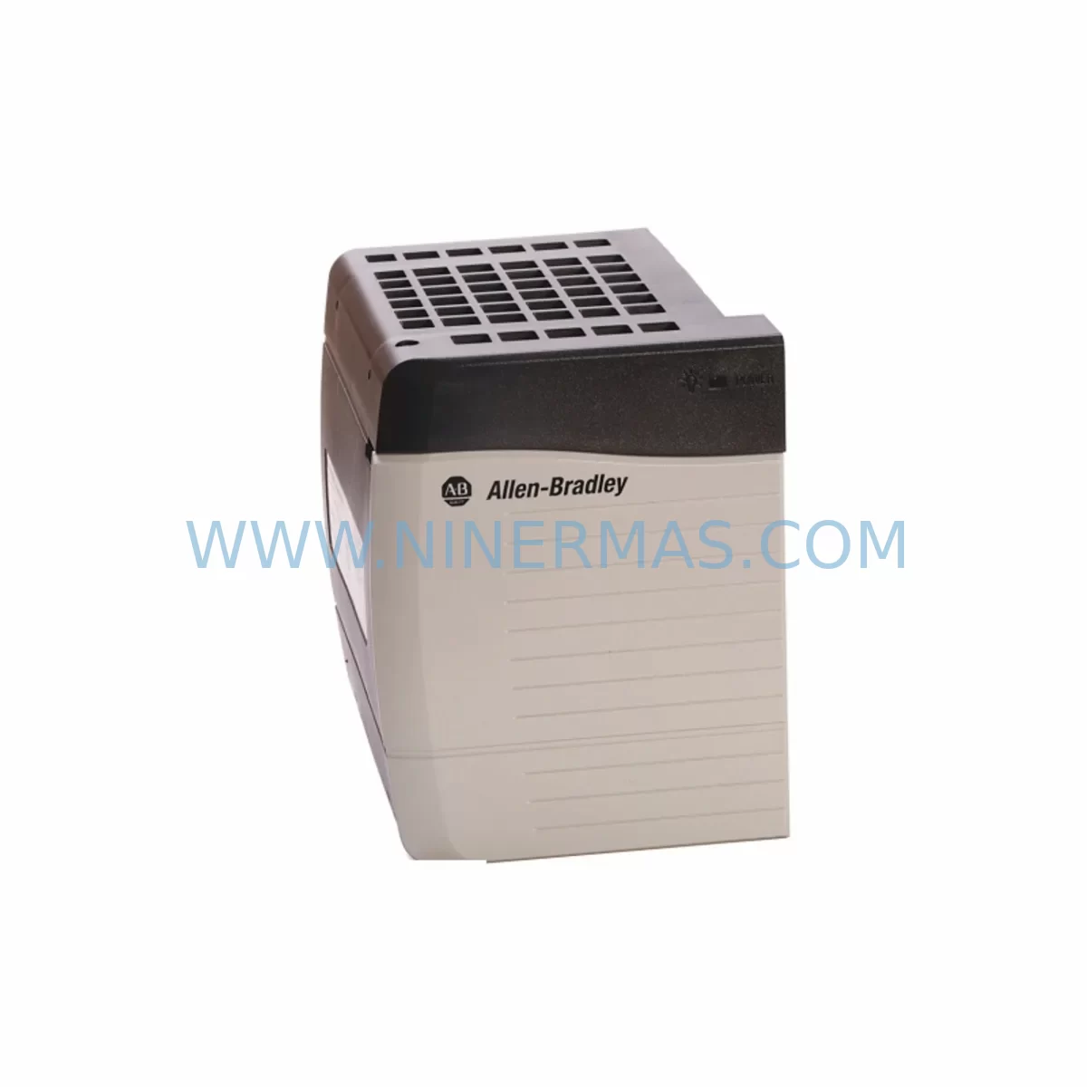
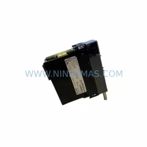
Allen-Bradley 1756-A10K Retrofit 10-Slot Chassis Legacy Systems
Verify the part, confirm the platform family, and move straight into quotation with the right commercial details.
RFQ Ready
- SKU1756-A10K
- CategorySIS Safety & Redundancy Systems
- BrandAllen-Bradley
- SupportAvailability, lead time, condition, and shipping coordination
How Buyers Usually Use This Page
- Confirm the exact part number and platform family before sending the quote request.
- Use direct email when quantity, condition, and destination are already defined internally.
- Switch to the broader brand or category archive when you need alternates nearby.
Series Navigation
Move through the most common platform families behind this part.
Product RFQ
Send this part directly for quotation.
Include quantity, required condition, destination country, and target delivery timing. Current reference: Allen-Bradley 1756-A10K Retrofit 10-Slot Chassis Legacy Systems with SKU 1756-A10K.
Allen-Bradley 1756-A10K Retrofit 10-Slot Chassis Legacy Systems: Legacy-Compatible Retrofit and Smooth Upgrade
The Allen-Bradley 1756-A10K is a 10-slot ControlLogix chassis designed for demanding industrial automation environments. As legacy ControlLogix installations age and original equipment reaches end-of-life, the 1756-A10K remains one of the most sought-after retrofit-compatible chassis solutions for maintenance engineers and system integrators managing aging control infrastructure. Whether you are replacing a failed chassis in an existing 1756 rack assembly, expanding I/O capacity in a legacy control cabinet, or migrating from an older PLC-5 or SLC 500 platform to a modern ControlLogix architecture, the 1756-A10K provides the physical and electrical foundation required for a reliable, low-risk upgrade.
NINERMAS maintains verified in-stock inventory of the 1756-A10K, sourced from authorized channels and subject to pre-shipment functional testing. Each unit ships with a 12-month warranty covering manufacturing defects and operational failures under normal industrial use conditions.
Upgrade Compatibility Table
| Parameter | Details |
|---|---|
| SKU / Part Number | 1756-A10K |
| Series | ControlLogix 1756 |
| Slot Count | 10 slots |
| Backplane Compatibility | Compatible with all 1756-series modules including processors, I/O, communication, and power supply modules |
| Power Supply Interface | Accepts 1756-PA75, 1756-PB75, 1756-PA72, and 1756-PB72 series power supplies |
| Communication Compatibility | Supports EtherNet/IP (1756-EN2T), ControlNet (1756-CNBR), DeviceNet, and serial communication modules |
| Replacement Recommendation | Direct chassis swap for existing 1756-A10 or 1756-A10K installations; verify module slot addressing after replacement |
| Installation Requirement | DIN rail or panel mount; confirm cabinet depth and width clearance before installation |
| Commissioning Focus | Verify backplane power distribution, module slot configuration, and I/O tree mapping in Studio 5000 / RSLogix 5000 |
| 12-Month Warranty | Covered under NINERMAS standard warranty; includes pre-shipment functional test report |
Retrofit Planning for Existing Automation Systems
When planning a retrofit around the 1756-A10K chassis, the first step is a thorough audit of the existing rack assembly. In most legacy installations, the chassis houses a combination of processor modules such as the 1756-L72 or 1756-L71, analog input modules like the 1756-IF16, digital output modules such as the 1756-OB16E, and digital input modules including the 1756-IB16I. Each of these modules must be catalogued with their current slot addresses before the chassis is removed, as slot addressing directly affects the I/O tree configuration stored in the controller program.
Power supply selection is equally critical. The 1756-A10K chassis is compatible with both the 1756-PA75 (120/240V AC input) and the 1756-PB75 (24V DC input) power supplies, as well as the lower-capacity 1756-PA72 and 1756-PB72 variants. Before committing to a chassis swap, calculate the total backplane current draw of all installed modules to confirm the existing power supply has sufficient capacity. Undersized power supplies are a common cause of intermittent faults following chassis replacements in legacy systems.
Communication architecture must also be reviewed. Many legacy ControlLogix installations rely on the 1756-EN2T EtherNet/IP communication module for integration with SCADA systems, historian platforms, and HMI panels. If the existing installation uses ControlNet for deterministic I/O communication, the 1756-CNBR ControlNet bridge module must be re-addressed and re-commissioned after the chassis swap. For installations that include remote I/O racks connected via a 1756-A7 or 1756-A13 chassis, the network topology and module addressing across all racks must be verified before the system is returned to service.
Terminal wiring and field device connections should be documented prior to any chassis removal. I/O modules with removable terminal blocks simplify this process, but fixed-terminal modules require careful labeling of each conductor before disconnection. Signal isolators installed between field devices and I/O modules should also be inspected during the retrofit to confirm they remain within calibration tolerances.
For installations migrating from older PLC-5 or SLC 500 platforms to ControlLogix, the 1756-A10K provides the physical rack infrastructure, but the migration also requires attention to program conversion, HMI screen updates, and communication protocol changes. In these cases, a 1769-L33ER CompactLogix controller may serve as an intermediate migration platform for smaller sub-systems before full consolidation into the 1756 ControlLogix architecture.
Downtime Control During System Migration
Minimizing unplanned downtime is the primary concern during any chassis replacement or system migration. A structured approach begins with a complete backup of the controller program, including all tag databases, I/O configurations, and motion profiles, using RSLogix 5000 or Studio 5000 Logix Designer before any hardware is disturbed. This backup should be stored on at least two independent media to protect against data loss during the physical swap.
Where production schedules permit, a planned maintenance window of four to eight hours is recommended for a straightforward chassis swap involving ten or fewer modules. During this window, the sequence should follow a defined order: power down the rack, document and photograph all module positions and wiring, remove modules in reverse slot order, install the replacement 1756-A10K chassis, reinstall modules in their original slot positions, reconnect all wiring, restore power, and verify the controller program download and I/O tree integrity before returning the system to automatic mode.
For critical production lines where extended downtime is not acceptable, a parallel commissioning approach can be used. A pre-configured replacement chassis assembly is built and tested offline, with the controller program loaded and verified against a simulated I/O environment. The live system is then switched to the replacement assembly during a brief scheduled outage, reducing the live changeover window to under one hour in most cases.
Throughout the migration, maintaining continuity of field control signals is essential. Where possible, manual control stations should be enabled to allow operators to maintain process control during the transition period. Communication links to SCADA and DCS systems should be monitored continuously, and alarm management procedures should be reviewed to prevent nuisance trips during the commissioning phase.
Retrofit Support FAQ
Q: Is the 1756-A10K a direct replacement for the original 1756-A10?
A: Yes. The 1756-A10K is the current catalog designation for the 10-slot ControlLogix chassis and is mechanically and electrically compatible with the original 1756-A10. All 1756-series modules, power supplies, and communication adapters that were compatible with the 1756-A10 are also compatible with the 1756-A10K. No program changes are required for a like-for-like chassis swap.
Q: What pre-shipment testing does NINERMAS perform on the 1756-A10K?
A: Each 1756-A10K unit undergoes a functional backplane test prior to shipment. This test verifies backplane power distribution, slot integrity, and physical connector condition. A test report is available upon request and is included with orders requiring documented traceability for maintenance records.
Q: How do I confirm the correct power supply for my 1756-A10K installation?
A: Calculate the total backplane current draw of all modules to be installed in the chassis. Compare this figure against the rated output current of the power supply (1756-PA75 provides 13A at 5V DC backplane; 1756-PA72 provides 10A). If the total module draw exceeds the power supply rating, a higher-capacity supply or a second chassis with its own power supply is required.
Q: What is the warranty coverage and lead time for the 1756-A10K?
A: NINERMAS provides a 12-month warranty on all 1756-A10K units covering manufacturing defects and operational failures under normal industrial use. Units in stock ship within 1–3 business days. For bulk orders or reserved inventory agreements, contact our sales team to discuss lead time commitments and long-term supply arrangements.
| Product Series | ControlLogix |
|---|---|
| Country of Origin | US |
Catalog Continuation
More Allen-Bradley modules in the catalog.
Use the brand lane to compare nearby part numbers, platform-adjacent modules, and other inquiry-ready listings before sending your final RFQ.
Catalog Continuation
Alternative parts within SIS Safety & Redundancy Systems.
Stay inside the same system family when you need substitutes, adjacent modules, or a broader shortlist for procurement review.