Original Industrial Spare Part
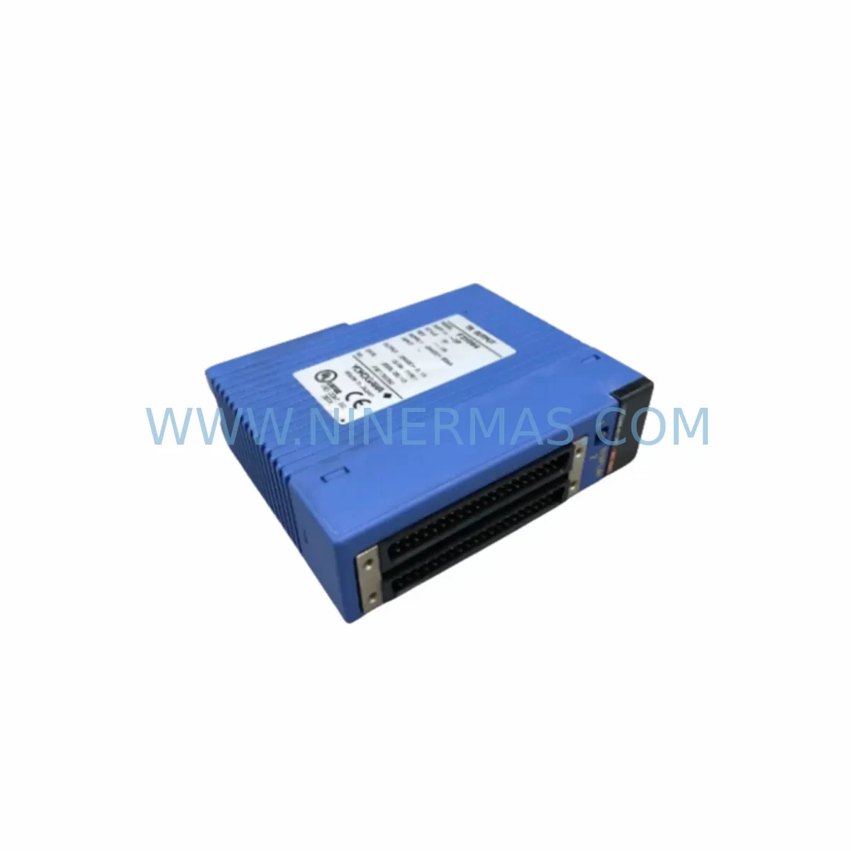
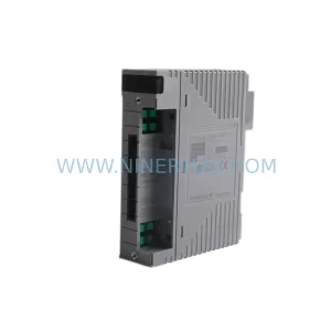
YOKOGAWA F3YD64-1F Retrofit-Compatible TR Output Module
Verify the part, confirm the platform family, and move straight into quotation with the right commercial details.
RFQ Ready
- SKUF3YD64-1F
- CategorySIS Safety & Redundancy Systems
- BrandYokogawa
- SupportAvailability, lead time, condition, and shipping coordination
How Buyers Usually Use This Page
- Confirm the exact part number and platform family before sending the quote request.
- Use direct email when quantity, condition, and destination are already defined internally.
- Switch to the broader brand or category archive when you need alternates nearby.
Series Navigation
Move through the most common platform families behind this part.
Product RFQ
Send this part directly for quotation.
Include quantity, required condition, destination country, and target delivery timing. Current reference: YOKOGAWA F3YD64-1F Retrofit-Compatible TR Output Module with SKU F3YD64-1F.
YOKOGAWA F3YD64-1F Retrofit-Compatible TR Output Module for Legacy FA-M3 Systems
The YOKOGAWA F3YD64-1F is a 64-point transistor (TR) output module designed for the YOKOGAWA FA-M3 and FA-M3R programmable controller platform. As a direct retrofit-compatible replacement for aging or discontinued output modules in legacy automation systems, the F3YD64-1F enables engineers and maintenance teams to extend the operational life of existing control architectures without requiring a full system overhaul. Whether you are managing a process plant, a discrete manufacturing line, or a utility control system, this module provides a reliable, field-proven output solution that integrates seamlessly into your existing FA-M3 backplane and rack infrastructure.
Industrial facilities running YOKOGAWA FA-M3 controllers often face the challenge of sourcing replacement I/O modules as original equipment reaches end-of-life. The F3YD64-1F addresses this directly by offering full backward compatibility with the FA-M3 rack system, including the F3BU04-0N, F3BU06-0N, and F3BU16-0N base units. Engineers can slot the F3YD64-1F into an existing rack without modifying the backplane wiring harness, preserving terminal block layouts and reducing the risk of miswiring during changeover. This is particularly valuable in environments where control cabinet space is constrained and downtime windows are measured in hours rather than days.
Before installing the F3YD64-1F as a replacement, maintenance engineers should verify several key parameters. Power supply capacity is the first checkpoint: confirm that the rack’s internal 5 VDC bus can support the additional current draw of a 64-point output module alongside co-installed modules such as the F3XD64-3N digital input module or F3AD08-6N analog input module. The FA-M3 power supply module — typically an F3PU20-0S or F3PU10-0S — should be checked against its rated output current before finalizing the retrofit plan.
Terminal wiring and load compatibility must also be confirmed. The F3YD64-1F uses NPN open-collector transistor outputs, and field devices connected to the previous module must be verified for compatibility with this output type. Solenoid valves, indicator lamps, relay coils, and motor starters driven through the output module should be checked for voltage and current ratings within the module’s specified range. If the legacy installation used relay output modules such as the F3YR16-1N, an interface relay or signal converter may be required to bridge the output type difference.
Module slot address and I/O mapping are critical steps in the retrofit process. The FA-M3 CPU — whether a F3SP71-4N, F3SP76-7N, or an older F3SP28-3N — assigns I/O addresses based on slot position within the rack. When replacing a module in an existing slot, the address mapping is typically preserved, but engineers must confirm this in the ladder logic program using YOKOGAWA’s WideField3 programming software before powering up the replacement module. Any changes to the I/O map will require corresponding updates to the PLC program and, where applicable, to HMI screen tag bindings in systems running YOKOGAWA ProSafe-RS or third-party SCADA platforms.
Communication link integrity should be verified if the FA-M3 system uses a network module such as the F3LE01-5T Ethernet interface or a F3LP02-0N PROFIBUS-DP module for integration with a DCS or supervisory system. Replacing an output module does not typically affect the communication layer, but a full I/O scan and forced-output test should be performed after installation to confirm that all 64 output points respond correctly before returning the system to automatic control.
Upgrade Compatibility Table
| Parameter | F3YD64-1F Specification | Retrofit Notes |
|---|---|---|
| Output Points | 64 points (NPN transistor) | Verify field devices are NPN-compatible; relay output legacy wiring may need interface relays |
| Rated Load Voltage | 12–24 VDC | Confirm field device operating voltage matches; check solenoid and relay coil ratings |
| Max Load Current per Point | 0.1 A | Verify inductive loads do not exceed rated current; add flyback diodes if required |
| Backplane Compatibility | FA-M3 / FA-M3R base units (F3BU04/06/16) | Direct slot replacement; no backplane modification required |
| Internal Bus Current (5 VDC) | Confirm with F3PU power supply rating | Check total rack current budget before installation |
| I/O Address Mapping | Slot-position based (FA-M3 standard) | Verify PLC program I/O map in WideField3 before power-up |
| Communication Compatibility | Compatible with FA-M3 CPU and network modules | No communication layer changes required for same-slot replacement |
| Installation Space | Standard FA-M3 module form factor | Fits existing cabinet cutout; no panel modification needed |
| Warranty | 12 Months | Covers manufacturing defects; pre-shipment functional test included |
Retrofit Planning for Existing Automation Systems
A successful retrofit of the F3YD64-1F into an existing FA-M3 system begins with a thorough site survey. Engineers should document the current module population across all racks, noting the slot positions of output modules, input modules, power supplies, and communication interfaces. In a typical FA-M3 control cabinet, you may find a mix of the F3XD32-3H 32-point digital input module, the F3YD32-1F 32-point transistor output module, and the F3AD04-1R analog input module operating alongside the CPU and network modules. Understanding the full rack configuration allows the retrofit team to calculate the total power budget and confirm that the existing F3PU20-0S power supply module can support the replacement without requiring an upgrade.
Terminal block wiring is one of the most time-sensitive tasks during a retrofit. The F3YD64-1F uses a 40-pin connector interface, and the field wiring harness from the previous module should be carefully labeled before disconnection. In installations where the original module used a different connector pitch or terminal arrangement, a wiring adapter or a new terminal block assembly may be required. Pre-fabricating the wiring harness off-site and testing it on a bench setup before the maintenance window significantly reduces the risk of wiring errors during the live changeover.
For systems that include an HMI — such as a YOKOGAWA UM33A panel meter or a third-party operator interface connected via Modbus or Ethernet — the output module replacement should be coordinated with an HMI tag review. Output status tags mapped to the replaced module’s I/O addresses should be verified against the updated PLC program to ensure that alarm states, interlock outputs, and manual override functions continue to operate correctly after the retrofit. Signal isolators or F3LC11-1F link controller modules used for inter-rack communication should also be checked to confirm that their output references remain valid.
Where the retrofit involves migrating from an older FA-M3 generation to the FA-M3R platform, engineers should review the CPU compatibility matrix. The F3SP76-7N and F3SP71-4N CPUs support the full FA-M3R I/O module range, and the F3YD64-1F is compatible with both generations. Programming cables such as the F9GT-RYCBL-5M or a standard USB-to-serial adapter with WideField3 software are required for program upload, verification, and forced-output testing during commissioning.
Downtime Control During System Migration
Minimizing production downtime during an FA-M3 output module replacement requires careful pre-planning and a structured changeover procedure. The recommended approach is to prepare a complete replacement kit — including the F3YD64-1F module, pre-labeled wiring harness, terminal block connectors, and a laptop with WideField3 installed — before the maintenance window begins. A pre-tested spare module that has been verified on a bench rack eliminates the risk of receiving a defective unit during a live changeover.
Before powering down the affected rack, the maintenance team should capture a full online backup of the PLC program using WideField3, including all I/O comments, data register values, and network configuration parameters. This backup serves as the recovery baseline if the replacement module requires any program adjustments. In systems where the FA-M3 CPU controls safety-critical outputs — such as emergency shutdown relays or process isolation valves — the safety interlock logic should be reviewed with the process engineer before any module is removed from service.
During the physical swap, the rack should be powered down in the correct sequence: first disable field power to the output terminals, then remove the module connector, and finally extract the module from the backplane slot. The F3YD64-1F can be inserted into the vacated slot without tools, and the connector should be seated firmly before restoring power. After power-up, a systematic forced-output test — cycling each of the 64 output points individually using WideField3’s monitor function — confirms that all field devices respond correctly before the system is returned to automatic mode.
For facilities that cannot tolerate a full rack shutdown, a partial migration strategy using a secondary rack with a F3BU06-0N base unit and a temporary F3PU10-0S power supply can be used to pre-stage the replacement module and verify its operation before the final cutover. This approach is particularly effective in continuous process environments where even a brief interruption to control outputs can trigger a process upset or safety shutdown.
Retrofit Support FAQ
Q1: Is the F3YD64-1F a direct replacement for the F3YD32-1F or other FA-M3 output modules?
The F3YD64-1F is a 64-point transistor output module and is not a pin-for-pin replacement for the 32-point F3YD32-1F. However, it is mechanically compatible with the same FA-M3 backplane slots. If you are replacing a 32-point module with the 64-point F3YD64-1F, the I/O address map in the PLC program will need to be updated to reflect the expanded point count, and the field wiring harness will need to be extended to connect all 64 output terminals.
Q2: What pre-shipment testing is performed on the F3YD64-1F before delivery?
Each F3YD64-1F unit supplied by NINERMAS undergoes a functional pre-shipment test that verifies all 64 output points for correct switching operation, internal bus communication, and LED status indication. Units that fail any test point are quarantined and not shipped. A 12-month warranty covering manufacturing defects and functional failures is included with every unit.
Q3: Can the F3YD64-1F be used in an FA-M3R system alongside newer CPU modules?
Yes. The F3YD64-1F is compatible with the FA-M3R platform and can be installed in the same rack as current-generation CPU modules such as the F3SP76-7N and F3SP71-4N. No firmware update or hardware modification is required. The module is recognized automatically by the FA-M3R CPU during rack initialization, and its I/O points are assigned based on slot position in the standard FA-M3 addressing scheme.
Q4: What is the lead time and inventory availability for the F3YD64-1F?
NINERMAS maintains stock of the F3YD64-1F to support urgent retrofit and breakdown replacement requirements. Standard orders are processed and dispatched within 1–3 business days. For large-quantity orders or long-term supply commitments supporting a lifecycle extension program, please contact our sales team to discuss a dedicated stock reservation arrangement. All units are supplied with a 12-month warranty from the date of shipment.
| Product Series | FA-M3 |
|---|---|
| Country of Origin | JP |
Catalog Continuation
More Yokogawa modules in the catalog.
Use the brand lane to compare nearby part numbers, platform-adjacent modules, and other inquiry-ready listings before sending your final RFQ.
Catalog Continuation
Alternative parts within SIS Safety & Redundancy Systems.
Stay inside the same system family when you need substitutes, adjacent modules, or a broader shortlist for procurement review.