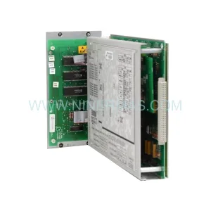
Original Industrial Spare Part
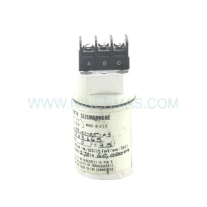
Bently Nevada 190501-24-00-04 Retrofit-Compatible Velomitor CT
Verify the part, confirm the platform family, and move straight into quotation with the right commercial details.
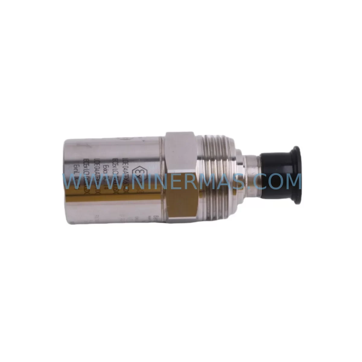
RFQ Ready
- SKU190501-24-00-04
- CategoryTSI & Rotating Machinery Monitoring
- BrandBently Nevada
- SupportAvailability, lead time, condition, and shipping coordination
How Buyers Usually Use This Page
- Confirm the exact part number and platform family before sending the quote request.
- Use direct email when quantity, condition, and destination are already defined internally.
- Switch to the broader brand or category archive when you need alternates nearby.
Series Navigation
Move through the most common platform families behind this part.
Product RFQ
Send this part directly for quotation.
Include quantity, required condition, destination country, and target delivery timing. Current reference: Bently Nevada 190501-24-00-04 Retrofit-Compatible Velomitor CT with SKU 190501-24-00-04.
Bently Nevada 190501-24-00-04 Retrofit-Compatible Velomitor CT for Legacy Systems
The Bently Nevada 190501-24-00-04 is a ruggedized Velomitor CT series velocity transducer engineered for continuous vibration monitoring in harsh industrial environments. As aging machinery protection systems reach end-of-life and OEM support for legacy platforms is discontinued, the 190501-24-00-04 has become a critical retrofit component for maintenance engineers tasked with sustaining plant uptime without committing to full system overhauls. Whether you are replacing a failed unit on an existing 3500 Series monitoring rack or upgrading a legacy Proximitor-based measurement chain, this module delivers drop-in compatibility with minimal re-engineering effort.
The Velomitor CT platform was designed to address the limitations of traditional piezoelectric velocity sensors in environments where temperature extremes, moisture ingress, and mechanical shock are routine. The 190501-24-00-04 variant incorporates ruggedized housing and extended temperature tolerance, making it particularly well-suited for compressor trains, steam turbine bearing housings, gearboxes, and pump skids operating in offshore, petrochemical, and power generation facilities. Its 4-20 mA output and integral signal conditioning eliminate the need for external signal isolators in most retrofit configurations, simplifying cabinet wiring and reducing the overall component count in the control loop.
Upgrade Compatibility Table
| Parameter | 190501-24-00-04 (This Unit) | Legacy / Predecessor Models |
|---|---|---|
| Series | Velomitor CT | Velomitor, 190501 standard variants |
| Output Signal | 4-20 mA (integral conditioning) | Voltage output (requires external conditioner) |
| Housing | Ruggedized, IP67-rated | Standard industrial housing |
| Temperature Range | -40°C to +121°C | -20°C to +85°C (standard) |
| Connector Interface | 2-pin MIL-spec connector | 2-pin standard (verify pin-out before swap) |
| Rack Compatibility | 3500 Series Monitor Rack | 3300, 3500 (confirm module address) |
| Communication | Hardwired 4-20 mA / Modbus via monitor | Hardwired analog |
| Mounting | M8 stud mount / adhesive pad | M8 stud (confirm thread engagement depth) |
| Retrofit Recommendation | Direct replacement with wiring verification | Check terminal block labeling on 3500/20 I/O module |
| Commissioning Note | Verify sensitivity scaling in 3500/42M or 3500/45 monitor | Re-enter transducer sensitivity if monitor was reset |
| Warranty | 12-Month Warranty — Covered from date of shipment | |
Retrofit Planning for Existing Automation Systems
Successful integration of the 190501-24-00-04 into an existing machinery protection architecture requires a structured pre-installation review. Begin by auditing the 3500/20 Rack Interface Module to confirm that the I/O terminal block assignments match the new transducer’s wiring scheme. In many legacy installations, the terminal labeling reflects the original sensor’s voltage output configuration, and the shift to a 4-20 mA loop-powered device requires updating the channel configuration within the 3500/42M Proximitor/Seismic Monitor or the 3500/45 Position Monitor, depending on which measurement function is being served.
Power supply capacity is a frequent oversight during retrofit planning. The 190501-24-00-04 draws loop power from the monitor’s internal supply rail, but if the rack is already near its power budget — particularly in dense configurations using the 3500/15 Power Supply Module — engineers should verify available headroom before adding additional loop-powered devices. In installations where the rack power supply is shared with a 3500/22M Transient Data Interface or a 3500/92 Communication Gateway Module, a supplemental 3500/05 Rack expansion may be warranted to distribute the load.
Backplane slot addressing must also be confirmed prior to installation. The 3500 Series rack uses a fixed slot-to-channel mapping, and inserting the replacement transducer into an incorrect monitor slot will result in mismatched alarm setpoints and trend data gaps in the System 1 Condition Monitoring Software historian. If the plant’s DCS or SCADA platform receives vibration data via Modbus TCP through the 3500/92 gateway, the register map should be validated after the swap to ensure that the new channel address is correctly mapped to the process control display.
For facilities running Bently Nevada TDXnet or legacy Data Manager 2000 historian platforms, a configuration export should be performed before the outage window begins. This preserves alarm thresholds, full-scale ranges, and transducer sensitivity values that would otherwise need to be re-entered manually — a process that can extend commissioning time significantly if documentation is incomplete. Where HMI faceplate graphics reference specific tag names tied to the old sensor’s channel, coordinate with the control system team to update the Wonderware InTouch or FactoryTalk View display bindings before returning the machine to service.
Cable routing and installation space should be assessed during the planning phase. The 190501-24-00-04’s ruggedized connector and cable assembly may have a larger bend radius than the predecessor unit, and in tight junction boxes or conduit entries, this can affect how the cable is dressed. Confirm that the existing 330130 extension cable or equivalent field wiring is rated for the ambient temperature and chemical exposure at the measurement point. If the original cable shows signs of insulation degradation, replacing it concurrently with the transducer eliminates a common source of post-retrofit signal noise.
Downtime Control During System Migration
Minimizing production impact during a Velomitor CT replacement requires advance preparation that begins well before the maintenance window opens. The most effective approach is to pre-configure a spare 3500/42M monitor card offline with the correct transducer type, sensitivity, and alarm setpoints cloned from the existing channel configuration. This allows the card swap and transducer replacement to proceed in parallel, reducing the time the machinery protection system operates in bypass mode.
Before entering bypass, notify the control room and confirm that the DCS has acknowledged the inhibit status for the affected measurement point. If the machine cannot be taken offline, a temporary portable vibration analyzer — such as a Bently Nevada SCOUT 100 or equivalent handheld device — can be used to maintain continuous vibration surveillance on the bearing housing while the permanent monitor channel is being serviced. This approach is particularly valuable on critical compressors or turbines where API 670 compliance requires uninterrupted protection coverage.
Program logic integrity should be verified before and after the swap. If the vibration channel feeds a safety instrumented function via a 3500/33 16-Channel Relay Module or interfaces with a Triconex Safety Controller through hardwired trip signals, the relay output states must be confirmed in the safe position before disconnecting the transducer. After reconnection, perform a loop check by applying a known vibration stimulus or using the monitor’s built-in self-test function to verify that the 4-20 mA signal is correctly received, scaled, and displayed before releasing the bypass inhibit.
Document all configuration changes, terminal assignments, and as-found versus as-left readings in the plant’s maintenance management system. This record supports future audits, insurance inspections, and the next planned maintenance interval, and it provides the baseline data needed to detect any drift in the new transducer’s output over its service life.
Retrofit Support FAQ
Q1: Is the 190501-24-00-04 a direct drop-in replacement for the standard 190501 Velomitor?
A: The 190501-24-00-04 shares the same mechanical mounting interface and general measurement function as the standard 190501 series, but its ruggedized housing and 4-20 mA output differ from voltage-output predecessors. Wiring terminations at the 3500/20 I/O module must be verified, and the monitor channel must be reconfigured to accept a current-loop input if the original installation used a voltage-output sensor. We recommend reviewing the channel configuration file before scheduling the replacement outage.
Q2: What commissioning steps are required after installation?
A: After physical installation and wiring, power up the 3500 rack and navigate to the affected channel in the monitor configuration software. Confirm that the transducer type is set to Velomitor CT, enter the sensitivity value from the unit’s calibration certificate, and verify that the full-scale range and alarm setpoints match the original configuration. Perform a loop check to confirm signal continuity, then release the bypass inhibit and observe the live vibration reading for at least 15 minutes before returning the machine to normal operation.
Q3: Do you provide pre-shipment testing, and what does the 12-month warranty cover?
A: Yes. Every 190501-24-00-04 unit undergoes functional verification and output signal testing prior to shipment. The 12-month warranty covers manufacturing defects and component failures under normal operating conditions from the date of shipment. It does not cover damage resulting from incorrect installation, overvoltage, or exposure to conditions beyond the rated specification. Warranty claims are processed with return authorization, and replacement units are dispatched from stock to minimize your downtime.
Q4: Is inventory available for immediate shipment?
A: We maintain stock of the 190501-24-00-04 to support urgent replacement requirements. Lead times for in-stock units are typically 3-5 business days for international shipments. For large-quantity orders or scheduled maintenance programs requiring multiple units, contact our sales team to confirm availability and arrange consolidated shipping to reduce freight costs.
| Product Series | 3500 series |
|---|---|
| Country of Origin | US |
Catalog Continuation
More Bently Nevada modules in the catalog.
Use the brand lane to compare nearby part numbers, platform-adjacent modules, and other inquiry-ready listings before sending your final RFQ.
SKU: 330910-00-11-10-01-00
Bently Nevada 330910-00-11-10-01-00 Safety-Reliable Proximity Transducer
SKU: 330881-16-00-175-00-02
Bently Nevada 330881-16-00-175-00-02 Safety Proximity Transducer
SKU: 330103-00-10-05-01-00
Bently Nevada 330103-00-10-05-01-00 Retrofit Proximity Probe
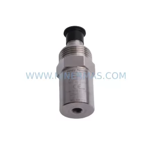
SKU: 190501-06-00-04
Bently Nevada 190501-06-00-04 Retrofit Velocity Transducer
Catalog Continuation
Alternative parts within TSI & Rotating Machinery Monitoring.
Stay inside the same system family when you need substitutes, adjacent modules, or a broader shortlist for procurement review.
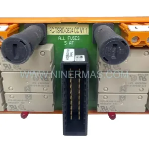
SKU: FC-TSRO-0824 CCV 1.1
Honeywell FC-TSRO-0824 CCV 1.1 SIL3 Relay Output Field Termination Assembly
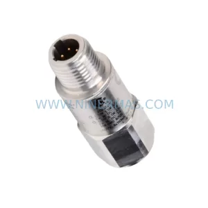
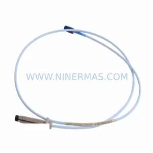
SKU: 330103-11-19-10-02-00
Bently Nevada 330103-11-19-10-02-00 3300 Series Retrofit
SKU: 21000-16-05-00-115-03-02
Bently Nevada 21000-16-05-00-115-03-02 Retrofit Proximity Probe