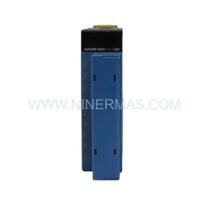
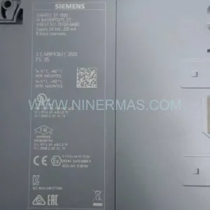
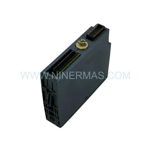
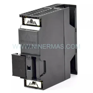
Original Industrial Spare Part
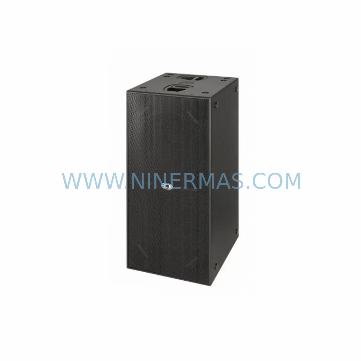
SUB28-0242-19783 Retrofit Thermal Module for Legacy Systems
Verify the part, confirm the platform family, and move straight into quotation with the right commercial details.
RFQ Ready
- SKUSUB28 0242-19783 10332-31000
- CategoryPLC & Industrial Automation Modules
- BrandSUB28
- SupportAvailability, lead time, condition, and shipping coordination
How Buyers Usually Use This Page
- Confirm the exact part number and platform family before sending the quote request.
- Use direct email when quantity, condition, and destination are already defined internally.
- Switch to the broader brand or category archive when you need alternates nearby.
Series Navigation
Move through the most common platform families behind this part.
Product RFQ
Send this part directly for quotation.
Include quantity, required condition, destination country, and target delivery timing. Current reference: SUB28-0242-19783 Retrofit Thermal Module for Legacy Systems with SKU SUB28 0242-19783 10332-31000.
SUB28-0242-19783 Retrofit Thermal Module for Legacy Systems
The SUB28-0242-19783 is a ruggedized direct radiator thermal management module engineered for continuous operation in harsh industrial environments. Designed as a retrofit-compatible replacement for legacy control cabinet cooling assemblies, this module addresses the growing challenge of maintaining thermal stability in aging automation infrastructure where original OEM components are no longer available through standard supply channels. Whether you are managing a legacy PLC enclosure, a drive control cabinet, or a distributed I/O rack in a manufacturing facility, the SUB28-0242-19783 provides a reliable, pre-tested thermal solution that integrates with existing mounting frames and wiring harnesses without requiring structural cabinet modifications.
Industrial maintenance engineers and system integrators working on end-of-life automation platforms frequently encounter thermal management failures as the first sign of broader system degradation. Cooling modules in legacy control cabinets — particularly those housing Siemens SIMATIC S5 or S7-300 series PLCs, ABB AC500 controllers, Lenze 8400 series drives, or Mitsubishi MELSEC Q-series racks — are subject to continuous thermal cycling that degrades fan bearings, heat sink efficiency, and airflow baffles over time. The SUB28-0242-19783 is stocked specifically to serve as a direct replacement in these retrofit scenarios, reducing the risk of unplanned downtime caused by thermal runaway or overtemperature shutdowns.
Before installing the SUB28-0242-19783 in a retrofit application, engineers should verify several critical parameters. Power supply compatibility is the first checkpoint: confirm that the existing cabinet power supply — whether a 24 VDC rail-mount unit or an integrated AC/DC converter — can support the module’s rated input voltage and current draw without exceeding the supply’s derating curve at ambient temperature. In cabinets where a Siemens SITOP PSU8200 or a Phoenix Contact QUINT-PS power supply is already installed, this verification is straightforward using the supply’s load curve documentation.
Terminal wiring and connector compatibility must also be confirmed prior to installation. The SUB28-0242-19783 uses a standard industrial terminal block interface compatible with 0.5–2.5 mm² conductors. In legacy cabinets where wiring was originally routed to a predecessor module using proprietary connectors, an adapter harness or re-termination to Phoenix Contact or Weidmüller terminal blocks may be required. Document all existing wire labels and conductor colors before disconnecting the original module to ensure accurate re-termination.
Backplane and rack interface considerations apply when the thermal module is mounted adjacent to active I/O modules or communication processors. In systems using Beckhoff EtherCAT terminals or B&R X20 I/O modules, ensure that the thermal module’s mounting position does not obstruct the bus connector alignment or interfere with the DIN rail grounding continuity. Verify that the module’s physical footprint matches the available slot width in the existing mounting frame.
For systems where the original thermal module was integrated with a supervisory control loop — for example, in Yokogawa CENTUM VP or Honeywell Experion PKS distributed control systems — confirm that the replacement module’s alarm output signal (typically a dry contact or 4–20 mA analog signal) is compatible with the existing DCS analog input card or digital input module. If the original module reported overtemperature status to an Omron CJ2M CPU or a Mitsubishi Q03UDECPU via a dedicated I/O channel, the replacement wiring must preserve this signal path to avoid masking thermal fault conditions in the SCADA or HMI display.
HMI screen and alarm tag updates should be planned as part of the retrofit scope. In facilities using Siemens WinCC, Wonderware InTouch, or FactoryTalk View SE, the thermal module’s alarm tags and trend displays may reference the original module’s I/O address. After re-termination, update the HMI tag database to reflect any address changes introduced by the replacement module’s wiring configuration. This step is frequently overlooked during rapid replacement scenarios and can result in masked alarms or incorrect trend data post-commissioning.
Communication link integrity must be maintained throughout the replacement process. In cabinets where PROFIBUS DP, PROFINET, or Modbus RTU communication cables pass through or near the thermal module’s mounting position, ensure that cable routing is not disturbed during removal and reinstallation. Use cable ties and ferrite cores to maintain EMC compliance after the retrofit is complete.
Installation space confirmation is essential before ordering. Measure the available depth, width, and height in the target cabinet section, accounting for door clearance and cable management channels. The SUB28-0242-19783’s ruggedized housing is designed for standard 19-inch rack or DIN rail mounting configurations, but verify the exact mounting pattern against your cabinet’s existing hardware before committing to the installation plan.
All units are pre-shipment tested under load conditions prior to dispatch and are covered by a 12-month warranty from the date of delivery.
Upgrade Compatibility Table
| Parameter | SUB28-0242-19783 (Replacement) | Retrofit Notes |
|---|---|---|
| Module Type | Ruggedized Direct Radiator Thermal Module | Drop-in replacement for legacy cooling assemblies |
| Mounting Interface | DIN Rail / 19-inch Rack | Verify existing rail type; adapter bracket may be required |
| Input Voltage | 24 VDC (nominal) | Confirm cabinet PSU derating at operating temperature |
| Terminal Wiring | 0.5–2.5 mm² screw terminal | Re-terminate if original used proprietary connectors |
| Communication Compatibility | Dry contact alarm output | Map to existing DI card or DCS analog input |
| Operating Environment | -20°C to +70°C, IP54 rated | Suitable for harsh industrial and outdoor enclosures |
| Replacement Scope | Legacy thermal / cooling modules in control cabinets | Confirm physical dimensions before ordering |
| Commissioning | No firmware configuration required | Verify alarm signal wiring and HMI tag update |
| Warranty | 12-Month Warranty from date of delivery; pre-shipment tested under load | |
Retrofit Planning for Existing Automation Systems
Successful integration of the SUB28-0242-19783 into an existing automation system requires a structured retrofit plan that accounts for the interdependencies between the thermal module and the surrounding control architecture. In a typical legacy control cabinet, the thermal management assembly operates alongside a range of components that must remain operational during the replacement window.
Begin by auditing the cabinet’s power distribution. In systems where a Siemens SITOP PSU8200 24V/20A or equivalent rail-mount power supply feeds both the PLC backplane and the thermal module, calculate the total load after replacement to confirm the supply remains within its rated output. If the cabinet also houses a Phoenix Contact QUINT-PS/1AC/24DC/10 redundant power supply module, verify that the redundancy switchover logic is not affected by the thermal module replacement sequence.
Next, assess the I/O architecture. In systems using Siemens ET 200SP distributed I/O or Beckhoff EK1100 EtherCAT couplers with terminal modules, confirm that the thermal module’s alarm output is correctly mapped to an available digital input channel. If the system uses a B&R X20DI9371 digital input module, verify the input voltage threshold compatibility with the replacement module’s dry contact output.
For cabinets controlling drives and motion systems — such as those housing a Lenze i550 series inverter or an ABB ACS880 drive — thermal management is critical to maintaining drive derating margins. Confirm that the replacement module’s airflow direction and heat dissipation capacity are compatible with the drive’s thermal envelope. In cabinets where a Mitsubishi FR-A800 series inverter is installed adjacent to the thermal module, ensure that the module’s fan exhaust does not recirculate hot air into the drive’s intake.
Communication infrastructure must be preserved throughout the retrofit. If the cabinet includes a PROFIBUS DP network segment with a Siemens CP 342-5 communication processor or a Modbus RTU link managed by an Omron CJ1W-SCU41-V1 serial communication unit, route replacement wiring away from these communication cables to avoid introducing EMI that could cause bus errors or communication timeouts during commissioning.
Finally, document the pre-retrofit baseline: record all I/O states, alarm statuses, and communication link health before beginning the replacement. This baseline allows rapid comparison during post-installation verification and supports the commissioning sign-off process required by most plant maintenance management systems.
Downtime Control During System Migration
Minimizing production downtime during a thermal module replacement requires careful pre-staging and a disciplined execution sequence. The SUB28-0242-19783 is designed to support rapid swap-out scenarios where the replacement window is constrained by production schedules or safety permit durations.
Before the planned maintenance window, pre-stage the replacement module with all required wiring harnesses, terminal adapters, and mounting hardware. Prepare a printed wiring diagram showing the original module’s terminal assignments alongside the replacement module’s terminal layout. This side-by-side reference eliminates re-termination errors under time pressure.
Protect the original program logic by performing a full PLC program backup immediately before the replacement begins. In systems using a Siemens S7-300 CPU or a Mitsubishi Q03UDECPU, use the programming software (STEP 7, GX Works2, or TIA Portal) to save the current program, data blocks, and hardware configuration to a secure offline location. This backup ensures that any accidental parameter loss during the cabinet work can be recovered without re-engineering the control logic.
Maintain field control continuity by confirming that any safety interlocks or emergency stop circuits associated with the thermal module’s alarm output are placed in a safe state before disconnecting the original module. In systems where the thermal alarm is wired into a safety relay — such as a Pilz PNOZ X series or a Schmersal SRB-E-301ST — follow the safety relay’s bypass procedure documented in the plant’s lock-out/tag-out (LOTO) protocol.
After installation, perform a staged power-up sequence: energize the cabinet power supply first, verify the thermal module’s status indicator, then restore the PLC and I/O power. Confirm that all alarm tags in the HMI are cleared and that the thermal module’s output signal is correctly received by the DCS or PLC input card before releasing the system to production. Total replacement time for a pre-staged SUB28-0242-19783 installation is typically 45–90 minutes, depending on cabinet access and wiring complexity.
Retrofit Support FAQ
Q1: Is the SUB28-0242-19783 a direct drop-in replacement for my existing thermal module?
The SUB28-0242-19783 is designed as a retrofit-compatible replacement for legacy ruggedized direct radiator modules used in industrial control cabinets. Physical dimensions, mounting interface, and terminal wiring should be verified against your existing installation before ordering. Contact our technical team with your cabinet drawings or original module part number for a compatibility confirmation.
Q2: What commissioning steps are required after installation?
No firmware or software configuration is required for the SUB28-0242-19783. After mechanical installation and wiring re-termination, verify the alarm output signal continuity, confirm the HMI alarm tag is active and correctly mapped, and perform a functional test by monitoring the module’s status indicator under normal operating load for a minimum of 30 minutes before returning the system to production.
Q3: Is the unit tested before shipment, and what warranty is provided?
Yes. Every SUB28-0242-19783 unit undergoes pre-shipment functional testing under load conditions before dispatch. All units are covered by a 12-month warranty from the date of delivery, covering manufacturing defects and premature component failure under normal operating conditions. Warranty claims are supported by our technical team at sale@ninermas.com.
Q4: What is the typical lead time and stock availability?
The SUB28-0242-19783 is maintained in ready-to-ship inventory to support urgent maintenance and unplanned downtime scenarios. Standard lead time for in-stock units is 3–5 business days for international shipments. For large-quantity orders or reserved inventory agreements for long-term maintenance contracts, contact our procurement team to discuss dedicated stock allocation and extended supply commitments.
| Product Series | Legacy |
|---|
Catalog Continuation
Alternative parts within PLC & Industrial Automation Modules.
Stay inside the same system family when you need substitutes, adjacent modules, or a broader shortlist for procurement review.
SKU: SCE906A2-002-01 SCE906A200201
Pacific Scientific SCE906A2-002-01 Retrofit Servo Amplifier
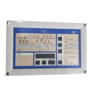
SKU: EPC500 3183062451
Alfa Laval EPC500 3183062451 Service-Ready Spare Part