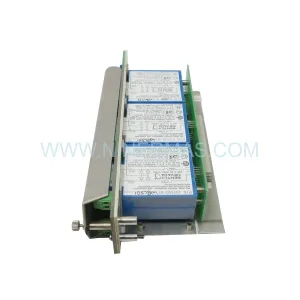
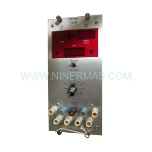
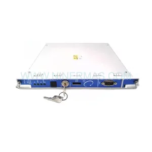
Original Industrial Spare Part
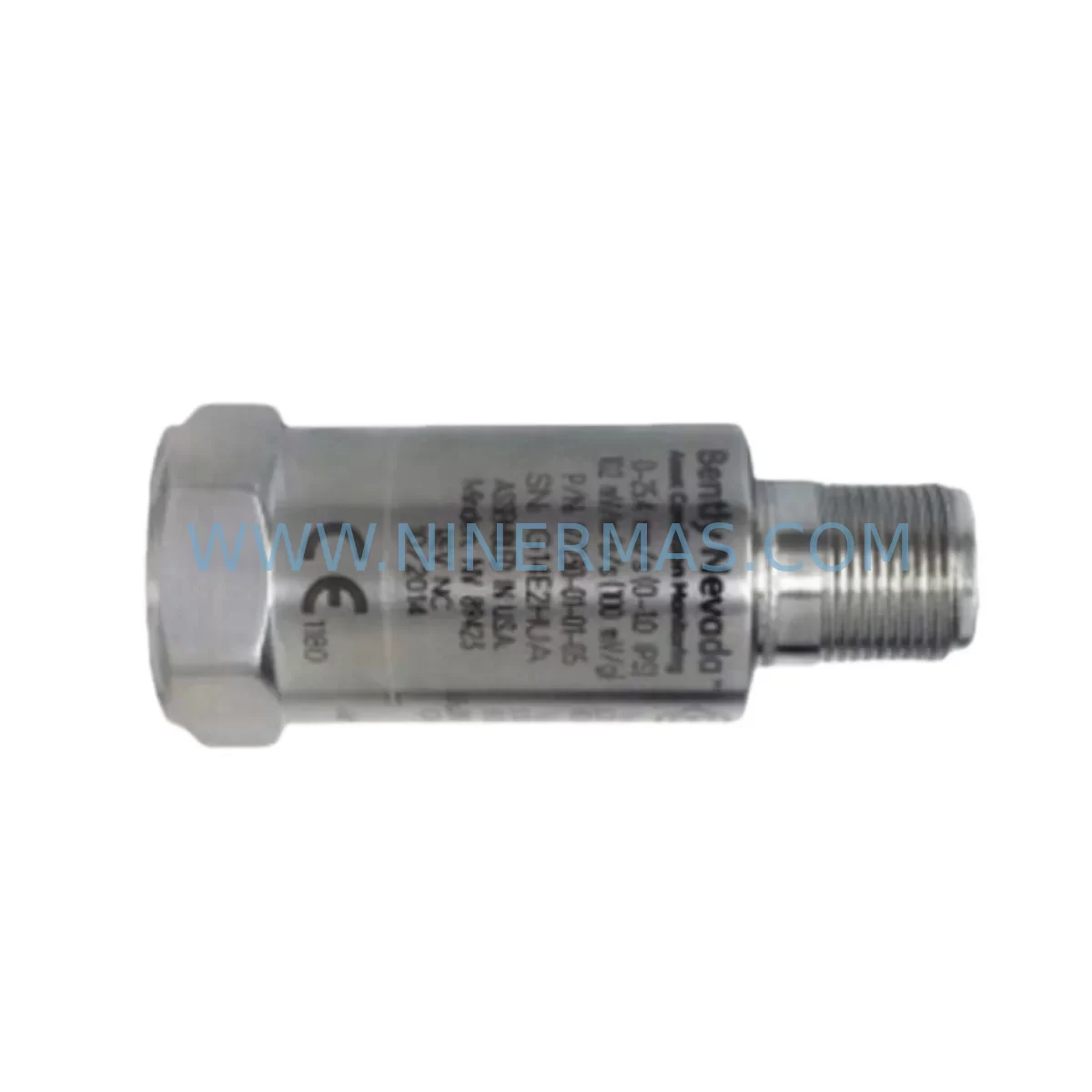
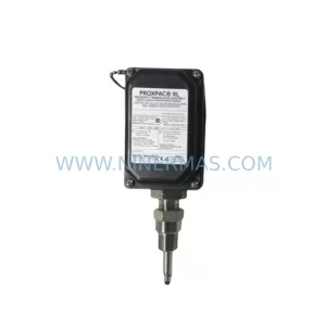
Bently Nevada 190501-16-00-04 Spare Part for Industry
Verify the part, confirm the platform family, and move straight into quotation with the right commercial details.
RFQ Ready
- SKU190501-16-00-04
- CategoryTSI & Rotating Machinery Monitoring
- BrandBently Nevada
- SupportAvailability, lead time, condition, and shipping coordination
How Buyers Usually Use This Page
- Confirm the exact part number and platform family before sending the quote request.
- Use direct email when quantity, condition, and destination are already defined internally.
- Switch to the broader brand or category archive when you need alternates nearby.
Series Navigation
Move through the most common platform families behind this part.
Product RFQ
Send this part directly for quotation.
Include quantity, required condition, destination country, and target delivery timing. Current reference: Bently Nevada 190501-16-00-04 Spare Part for Industry with SKU 190501-16-00-04.
Bently Nevada 190501-16-00-04 Service-Ready Spare Part for Industrial Maintenance
The Bently Nevada 190501-16-00-04 is a ruggedized velocity transducer module designed for continuous vibration monitoring in demanding industrial environments. As a critical spare part within the Velomitor CT series, this unit delivers reliable seismic velocity measurement for rotating machinery protection systems, including turbines, compressors, pumps, and motors. Maintenance engineers and procurement teams managing aging automation infrastructure rely on this component to minimize unplanned downtime and extend the operational life of existing control architectures.
Whether you are managing a scheduled annual overhaul, responding to an unexpected sensor fault, or building a strategic spare parts inventory, the 190501-16-00-04 is a direct service replacement that integrates seamlessly into existing Bently Nevada 3500 Series machinery protection racks. Its ruggedized construction ensures stable performance in high-vibration, high-temperature plant environments where sensor reliability is non-negotiable.
Spare Maintenance Table
| Parameter | Specification / Details |
|---|---|
| Part Number | 190501-16-00-04 |
| Brand | Bently Nevada |
| Series | Velomitor CT Series |
| Product Type | Ruggedized Velocity Transducer Module |
| Measurement Type | Seismic Velocity (mm/s or in/s) |
| Output Signal | Velocity (integrated from accelerometer) |
| Compatible System | Bently Nevada 3500 Machinery Protection System |
| Mounting | Direct mount to machinery casing; standard transducer thread |
| Environmental Rating | Ruggedized for high-vibration, industrial plant environments |
| Application | Turbines, compressors, pumps, motors, fans |
| Replacement Compatibility | Drop-in replacement for same Velomitor CT series variants |
| Country of Origin | United States |
| Pre-shipment Testing | Yes — function and output verified before dispatch |
| Warranty | 12 Months |
Maintenance Planning for Continuous Operation
Effective maintenance planning for systems using the 190501-16-00-04 requires a holistic view of the surrounding instrumentation and control infrastructure. When replacing this velocity transducer, maintenance engineers should simultaneously inspect the Bently Nevada 3500/42M velocity monitor module, which processes the transducer’s output signal and triggers alarms or shutdowns based on configured setpoints. A faulty or miscalibrated monitor card can mask transducer faults or generate false trips even after a successful sensor replacement.
The transducer cable assembly — typically a shielded, low-capacitance coaxial cable routed from the machinery casing to the junction box — should be inspected for insulation damage, connector corrosion, and shield continuity. Damaged cabling is a frequent root cause of signal noise that is often misattributed to the transducer itself. Ensure the Bently Nevada 330130 or equivalent extension cable is intact and properly terminated at both ends.
Within the control cabinet, the 3500 rack power supply module (such as the 3500/15) should be verified for stable DC output voltage. Voltage fluctuations or ripple on the power rail can introduce measurement errors in sensitive vibration transducers. If the rack houses multiple I/O modules — including 3500/40M proximity monitor cards or 3500/50 tachometer input modules — confirm that the total power budget is within the rack’s rated capacity after any module swap.
For systems integrated with a DCS or PLC via the 3500/92 communication gateway module, verify that the Modbus or Ethernet/IP communication link remains active during the replacement window. If the transducer replacement requires a brief rack power cycle, coordinate with the control room to suppress alarms and prevent spurious shutdown signals from propagating to the distributed control system.
Signal isolators installed between the 3500 rack and the DCS analog input cards should also be checked. Devices such as Phoenix Contact MACX analog signal conditioners or equivalent DIN-rail-mounted isolators can degrade over time, introducing offset errors that appear as drift in the vibration trend data. Replacing the transducer without verifying isolator performance may result in persistent measurement inaccuracies post-maintenance.
Finally, if the plant uses a System 1 Evolution or similar condition monitoring software platform connected to the 3500 rack, confirm that the new transducer’s sensitivity and engineering unit configuration are correctly entered in the software database. Mismatched sensitivity values will produce incorrect velocity readings and may trigger nuisance alarms during post-replacement commissioning.
Site Replacement Workflow
Replacing the Bently Nevada 190501-16-00-04 on an active production site requires careful coordination to minimize downtime and maintain system integrity throughout the process.
Step 1 — Pre-replacement verification: Confirm the replacement unit’s part number, revision level, and sensitivity specification match the installed unit. Review the existing wiring diagram and terminal assignment for the transducer circuit. Notify the control room and obtain a work permit if the machinery is in service.
Step 2 — Signal bypass and alarm suppression: If the machinery cannot be taken offline, coordinate with the DCS operator to place the affected channel in bypass mode within the 3500 monitor. This prevents a false trip during the transducer swap. Document the bypass start time in the maintenance log.
Step 3 — Physical replacement: Disconnect the transducer cable at the junction box. Remove the old transducer from the machinery casing, noting the mounting torque and thread condition. Install the new 190501-16-00-04 to the specified torque. Reconnect the cable, ensuring the shield is grounded at one end only to prevent ground loops.
Step 4 — Signal verification: Power the circuit and verify the output signal at the 3500 monitor input terminals using a calibrated millivolt meter or the monitor’s front-panel display. Confirm the reading is within the expected range for the machinery’s current operating speed and load.
Step 5 — Alarm reinstatement and documentation: Remove the bypass, confirm alarm setpoints are active, and observe the vibration trend for a minimum of 15 minutes to verify stable, noise-free signal output. Update the maintenance record with the replacement date, new unit serial number, and post-replacement readings.
Spare Parts Support FAQ
Q1: Is the 190501-16-00-04 a direct drop-in replacement for other Velomitor CT variants?
The 190501-16-00-04 is a specific variant within the Velomitor CT series, differentiated by its connector type, cable length, and environmental rating suffix. Before ordering, confirm that the last four digits of your installed part number match, as different suffix combinations indicate different mechanical or electrical configurations. Our technical team can assist with cross-referencing if you provide the full installed part number and application details.
Q2: How is the unit tested before shipment?
Every 190501-16-00-04 unit is functionally tested prior to dispatch. Testing includes output signal verification, insulation resistance check, and connector integrity inspection. A test report is available upon request. Units are packaged in anti-static, shock-protected packaging to prevent transit damage.
Q3: Can you supply this part for long-term or blanket purchase orders?
Yes. We maintain stock of Bently Nevada Velomitor CT series components and can support scheduled delivery programs, annual maintenance contracts, and emergency same-day dispatch for critical plant situations. Contact our sales team to discuss volume pricing and lead time commitments.
Q4: What does the 12-month warranty cover?
The 12-month warranty covers manufacturing defects, premature component failure under normal operating conditions, and output signal deviation beyond the published specification. Warranty claims require the unit to be returned for inspection. Physical damage caused by incorrect installation, overvoltage, or environmental exposure beyond the rated specification is not covered. Our after-sales team will guide you through the warranty process promptly.
| Product Series | 3500 series |
|---|---|
| Country of Origin | US |
Catalog Continuation
More Bently Nevada modules in the catalog.
Use the brand lane to compare nearby part numbers, platform-adjacent modules, and other inquiry-ready listings before sending your final RFQ.
SKU: 330103-00-14-10-02-CN
Bently Nevada 330103-00-14-10-02-CN Retrofit Proximity Probe
SKU: 330704-000-060-10-02-CN
Bently Nevada 330704-000-060-10-02-CN 3300 XL Probe
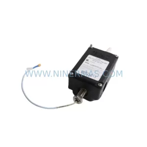
SKU: 31000-00-00-00-070-03-02
Bently Nevada 31000-00-00-00-070-03-02 Service-Ready Spare Part for Industrial Maintenance
Catalog Continuation
Alternative parts within TSI & Rotating Machinery Monitoring.
Stay inside the same system family when you need substitutes, adjacent modules, or a broader shortlist for procurement review.
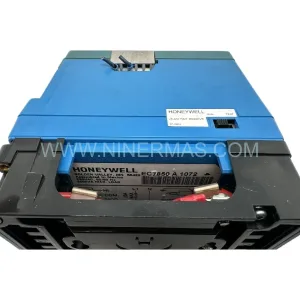
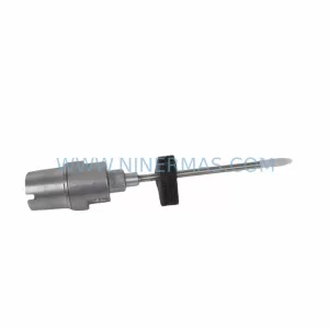
SKU: 21000-28-10-00-167-04-02
Bently Nevada 21000-28-10-00-167-04-02 Retrofit Proximity Probe
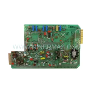
SKU: 330880-16-15-020-01-02
Bently Nevada 330880-16-15-020-01-02 Service-Ready Spare Part