Original Industrial Spare Part
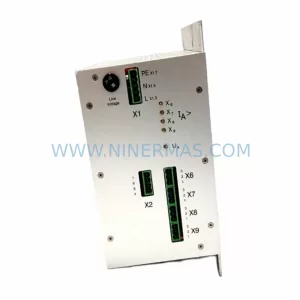
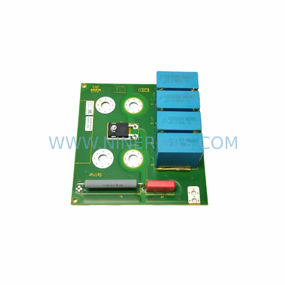
Danfoss 175Z2330 DT1 Service-Ready Spare Part for Industrial Maintenance
Verify the part, confirm the platform family, and move straight into quotation with the right commercial details.
RFQ Ready
- SKU175Z2330 DT1
- CategoryPLC & Industrial Automation Modules
- BrandDanfoss
- SupportAvailability, lead time, condition, and shipping coordination
How Buyers Usually Use This Page
- Confirm the exact part number and platform family before sending the quote request.
- Use direct email when quantity, condition, and destination are already defined internally.
- Switch to the broader brand or category archive when you need alternates nearby.
Series Navigation
Move through the most common platform families behind this part.
Product RFQ
Send this part directly for quotation.
Include quantity, required condition, destination country, and target delivery timing. Current reference: Danfoss 175Z2330 DT1 Service-Ready Spare Part for Industrial Maintenance with SKU 175Z2330 DT1.
Danfoss 175Z2330 DT1 Service-Ready Spare Part for Industrial Maintenance
The Danfoss 175Z2330 DT1 is an original relay module designed for integration within Danfoss VLT series frequency converters and associated industrial control cabinets. As a service-ready spare part, it is sourced directly from the Danfoss supply chain and tested prior to dispatch, ensuring drop-in compatibility with existing drive architectures. For maintenance engineers managing aging automation infrastructure, securing a verified replacement for the 175Z2330 DT1 is a critical step in reducing unplanned downtime and sustaining continuous production output.
In industrial environments where Danfoss VLT drives govern motor control across conveyor lines, pump stations, HVAC systems, and process automation cells, the relay output module plays a pivotal role in signalling fault states, enabling safe-stop sequences, and interfacing with external PLC inputs. A degraded or failed relay module can cascade into broader system faults — triggering nuisance trips, masking real fault conditions, or preventing controlled shutdowns. Stocking the 175Z2330 DT1 as a verified spare eliminates the procurement lead time risk that typically extends emergency downtime from hours into days.
NINERMAS supplies the Danfoss 175Z2330 DT1 as an original spare part with full traceability, pre-shipment functional testing, and a 12-month warranty covering manufacturing defects and operational failure under normal service conditions. Global logistics support ensures delivery to plant sites across Asia, Europe, the Middle East, and the Americas.
Spare Maintenance Table
| Part Number | 175Z2330 |
| Series / Variant | DT1 |
| Brand | Danfoss |
| Component Type | Relay Output Module |
| Compatible Platform | Danfoss VLT Series Frequency Converters (FC-Series) |
| Relay Contact Rating | Typically 240 VAC / 2 A (resistive load) — confirm with drive documentation |
| Output Function | Digital relay output for fault signalling, run/stop indication, external interlock |
| Installation Type | Internal module — plug-in or screw-mount per drive frame size |
| Operating Temperature | -10°C to +50°C (derate above 40°C per Danfoss guidelines) |
| Enclosure / Environment | IP20 internal; suitable for control cabinet installation |
| Origin | Denmark (Danfoss OEM) |
| Condition | Original New — pre-shipment tested |
| Warranty | 12 Months from date of dispatch |
| Maintenance Recommendation | Inspect relay contacts during annual drive service; replace if contact resistance exceeds threshold or relay fails self-test |
Maintenance Planning for Continuous Operation
When scheduling replacement of the Danfoss 175Z2330 DT1 relay module, a comprehensive maintenance review of the surrounding drive and control cabinet components is strongly recommended. Relay module failures rarely occur in isolation — they are often preceded or accompanied by stress on adjacent components within the same electrical circuit.
Begin with the Danfoss VLT control card (e.g., 175Z0401 or equivalent FC-series control board), which governs relay output logic and drive parameter execution. A faulty control card can generate false relay switching cycles that accelerate contact wear on the 175Z2330 DT1. Simultaneously, inspect the 24 VDC internal power supply module that feeds the control electronics — undervoltage conditions are a common root cause of intermittent relay behaviour.
Check the terminal block wiring at relay output terminals (typically terminals 01–03 on standard VLT frames) for signs of arcing, loose crimps, or insulation degradation. Corroded or undersized ferrule-terminated conductors at the relay output can introduce resistance that mimics a failing relay contact. Replace any suspect DIN rail terminal blocks or Phoenix Contact or Weidmüller-type feed-through terminals in the same wiring run.
For drives integrated into a PLC-controlled system, verify the digital input module on the PLC side that reads the relay feedback signal. A failed relay module may have already sent erroneous signals that triggered latched fault states in the Siemens S7 or Allen-Bradley ControlLogix I/O module receiving the contact closure. Clear and re-validate all associated I/O mappings after relay replacement.
Where the VLT drive communicates over Profibus DP or Modbus RTU, inspect the fieldbus communication option card (e.g., Danfoss FC Option B or C series) for firmware integrity and connector seating. Communication faults can mask relay status reporting at the SCADA or HMI level. If the site uses a Danfoss LCP (Local Control Panel), confirm that the display correctly reflects relay output status post-replacement.
Finally, review the input fuse or circuit breaker protecting the relay output circuit, and inspect any surge protection or varistor (MOV) devices fitted across inductive relay loads. These protective components absorb switching transients and should be replaced on a scheduled basis to prevent relay contact damage on the new 175Z2330 DT1 module.
Site Replacement Workflow
Step 1 — Isolation and Lockout: Isolate the Danfoss VLT drive from mains supply and apply LOTO (Lockout/Tagout) procedure. Allow a minimum 4-minute discharge period for DC bus capacitors before opening the drive enclosure.
Step 2 — Document Existing Configuration: Before removing the 175Z2330 DT1, photograph or record all relay output terminal wiring (terminals 01, 02, 03 or equivalent per frame). Note the drive parameter settings for relay output function (typically parameter group 5-4x in VLT FC series) using the LCP or PC-based MCT 10 software.
Step 3 — Module Removal: Disconnect relay output wiring at the terminal block. Release the module retention clip or unscrew the mounting fastener per the applicable VLT frame service manual. Extract the module carefully to avoid damage to the connector pins on the control card interface.
Step 4 — Inspect and Clean: Inspect the control card connector interface for oxidation or bent pins. Clean with isopropyl alcohol if required. Verify that the replacement 175Z2330 DT1 part number and DT1 variant marking match the removed unit.
Step 5 — Install Replacement Module: Seat the new 175Z2330 DT1 firmly into the control card interface. Reconnect relay output wiring per the documented terminal layout. Torque terminal screws to the specified value (typically 0.5–0.6 Nm for VLT control terminals).
Step 6 — Commissioning and Verification: Restore power and perform a relay output function test via the LCP or MCT 10 software. Confirm that the PLC or SCADA system correctly reads the relay state change. Log the replacement in the site maintenance record with the new module serial number and warranty start date.
This workflow minimises drive downtime to a single planned maintenance window and ensures full system compatibility is restored before returning the drive to production service.
Spare Parts Support FAQ
Q1: Is the Danfoss 175Z2330 DT1 an original part or a compatible aftermarket replacement?
The 175Z2330 DT1 supplied by NINERMAS is an original Danfoss spare part sourced through authorised industrial distribution channels. It is not an aftermarket or third-party compatible substitute. Each unit carries Danfoss OEM part markings and is subject to pre-shipment functional testing before dispatch.
Q2: What is the warranty coverage and how is a claim initiated?
All units are covered by a 12-month warranty from the date of dispatch, covering manufacturing defects and operational failure under normal service conditions. To initiate a warranty claim, contact NINERMAS at sale@ninermas.com with the order reference, installation date, and a description of the fault. Replacement or credit will be processed upon fault verification.
Q3: How do I confirm compatibility with my specific Danfoss VLT drive model before ordering?
Compatibility is confirmed by cross-referencing the 175Z2330 part number against your drive’s service manual or the Danfoss spare parts catalogue for your specific FC-series frame size and software version. NINERMAS technical support can assist with compatibility verification — provide your drive nameplate data (model number, power rating, software version) when enquiring.
Q4: Can NINERMAS support long-term or repeat supply of the 175Z2330 DT1 for multi-site maintenance programmes?
Yes. NINERMAS maintains stock and sourcing relationships to support long-term spare parts programmes for industrial clients managing multiple Danfoss VLT installations. Blanket purchase orders, scheduled delivery agreements, and volume pricing are available. Contact sale@ninermas.com or call +0086 187 5021 5667 to discuss your site’s annual maintenance requirements.
| Product Series | Other series |
|---|---|
| Country of Origin | DK |
Catalog Continuation
More Danfoss modules in the catalog.
Use the brand lane to compare nearby part numbers, platform-adjacent modules, and other inquiry-ready listings before sending your final RFQ.
SKU: FCD322 FCD322PT4P66STR1D0F00T52C0
DANFOSS FCD322PT4P66STR1D0F00T52C0 Service-Ready Spare Part
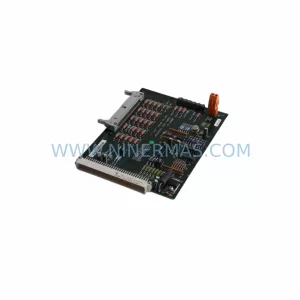
SKU: FCD 311 FCD311PT4P66STR1DCF00T62C0
Danfoss FCD311PT4P66STR1DCF00T62C0 Retrofit VFD for Legacy Systems
Catalog Continuation
Alternative parts within PLC & Industrial Automation Modules.
Stay inside the same system family when you need substitutes, adjacent modules, or a broader shortlist for procurement review.
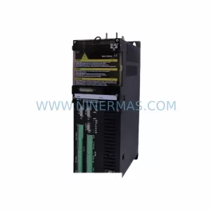
SKU: PMC-2/11/05/000/00/00/00/00/2K
ELAU PMC-2/11/05/000/00/00/00/00/2K Service-Ready Spare Part
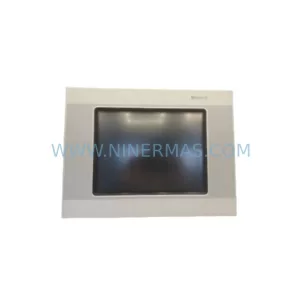
SKU: XVC-601-GTI-10-DPM-V1-000
Eaton XVC-601-GTI-10-DPM-V1-000 Service-Ready Spare Part
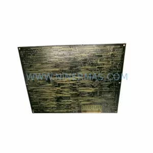
SKU: F31X139APMALG2FR01
GE F31X139APMALG2FR01 Service-Ready Spare Part for Industrial Maintenance
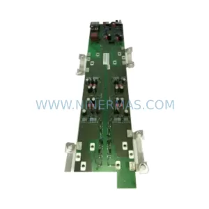
SKU: 6SE7038-6EK84-1JC1
Siemens 6SE7038-6EK84-1JC1 Retrofit-Compatible AC Drive for Legacy