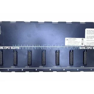
Original Industrial Spare Part
ASML 4022.437.0126 Service-Ready Spare for Industrial Maintenance
Verify the part, confirm the platform family, and move straight into quotation with the right commercial details.
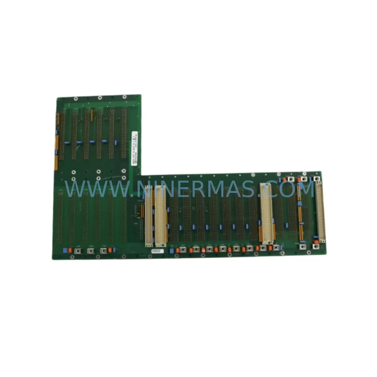
RFQ Ready
- SKU4022.437.0126 245799, 0190-25307 650PM-24CG-ADI1 0140-80495
- CategoryPLC & Industrial Automation Modules
- BrandASML
- SupportAvailability, lead time, condition, and shipping coordination
How Buyers Usually Use This Page
- Confirm the exact part number and platform family before sending the quote request.
- Use direct email when quantity, condition, and destination are already defined internally.
- Switch to the broader brand or category archive when you need alternates nearby.
Series Navigation
Move through the most common platform families behind this part.
Product RFQ
Send this part directly for quotation.
Include quantity, required condition, destination country, and target delivery timing. Current reference: ASML 4022.437.0126 Service-Ready Spare for Industrial Maintenance with SKU 4022.437.0126 245799, 0190-25307 650PM-24CG-ADI1 0140-80495.
ASML 4022.437.0126 Service-Ready Spare for Industrial Maintenance
The ASML 4022.437.0126 is a ruggedized PCB assembly module engineered for deployment in harsh semiconductor fabrication environments. Designed to meet the demanding operational requirements of ASML PAS and TWINSCAN lithography platforms, this module serves as a critical electronic assembly within the system’s control and signal processing architecture. For maintenance engineers managing fab uptime and procurement engineers building resilient spare parts inventories, securing a verified, service-ready replacement unit of the 4022.437.0126 is a foundational step in any preventive maintenance or emergency recovery plan.
Unplanned downtime in semiconductor lithography operations carries significant financial consequences. A single tool outage can halt wafer production across an entire process node. The 4022.437.0126 module, when it fails or degrades, can trigger cascading faults across interconnected subsystems. Having a pre-tested, warehouse-ready spare eliminates the lead time risk associated with OEM procurement channels, which may extend to weeks or months for end-of-life ASML components. NINERMAS maintains long-term stock agreements and pre-shipment functional testing protocols to ensure every unit shipped is ready for immediate installation.
Spare Maintenance Table
| Parameter | Specification / Detail |
|---|---|
| Part Number | 4022.437.0126 |
| Manufacturer | ASML |
| Module Type | Ruggedized PCB Assembly Module |
| Series Compatibility | ASML PAS Series, TWINSCAN Platform |
| Application Environment | Semiconductor Fab, Cleanroom Class 1–100, Harsh EMI/Vibration Conditions |
| Board Construction | Multi-layer ruggedized PCB with conformal coating |
| Connector Interface | Backplane-compatible, proprietary ASML edge connector |
| Operating Temperature | 0°C to +55°C (ambient, within enclosure) |
| Signal Type | Mixed analog/digital signal processing |
| Replacement Scope | Direct drop-in replacement for OEM unit; no firmware re-flash required in most configurations |
| Pre-Shipment Testing | Functional bench test, visual inspection, ESD-safe packaging |
| Origin | Netherlands (ASML OEM) |
| Warranty | 12 Months from date of shipment |
| Stock Status | Service-Ready | Long-Term Supply Available |
Maintenance Planning for Continuous Operation
When replacing the ASML 4022.437.0126 PCB assembly module, a thorough site inspection of the surrounding electrical and control architecture is essential to prevent repeat failures and ensure system stability. Maintenance engineers should treat this replacement as an opportunity to audit the full control cabinet and associated subsystems.
Begin with the backplane assembly that hosts the 4022.437.0126. Backplane connectors in high-vibration fab environments are prone to micro-arcing and contact oxidation. Inspect the backplane for bent pins, contamination, or thermal discoloration before seating the replacement module. Adjacent to the backplane, the ASML power supply module (typically within the 4022.4xx.xxxx series) should be load-tested; a degraded power rail is a common root cause of PCB module failure and will damage a new replacement if left unaddressed.
The I/O interface boards connected to the 4022.437.0126 should be inspected for signal integrity. Loose ribbon cables, corroded terminal blocks, or failed optocouplers on adjacent I/O cards can introduce noise that stresses the replacement module. If the system uses signal isolation modules between the PCB assembly and field devices, verify their isolation resistance and output linearity — degraded isolators are frequently overlooked during fault diagnosis.
Check all relay modules in the same control loop. Relay contacts in lithography tool control circuits experience high switching cycles and may exhibit contact bounce or welding that corrupts the signal environment for the new PCB module. Similarly, inspect fuse holders and protection fuses on the 24VDC and 5VDC rails feeding the module bay — a blown fuse that was replaced without root-cause analysis may indicate an upstream short that will recur.
For systems with communication modules (PROFIBUS, DeviceNet, or proprietary ASML serial interfaces), verify bus termination resistors and cable shielding continuity. A degraded communication link can cause the 4022.437.0126 to log spurious faults post-replacement, leading to misdiagnosis. If the tool uses an HMI panel for operator interface, confirm that the HMI firmware version is compatible with the replacement module’s revision level — ASML occasionally issues firmware dependencies between PCB assemblies and HMI software builds.
Finally, review the cable harness assemblies connecting the module bay to sensors, actuators, and the main controller. Chafed insulation, strained connectors, or improperly routed cables in the control cabinet are a leading cause of intermittent faults that are incorrectly attributed to PCB module failure. A complete cable audit during the replacement window reduces the risk of a repeat callout and extends the service interval of the newly installed 4022.437.0126.
Site Replacement Workflow
The following workflow is recommended for field engineers replacing the ASML 4022.437.0126 in a live production environment:
- Pre-Replacement Audit: Document the current system fault log, capture all active alarms, and photograph the existing module’s installation orientation and cable routing before removal.
- Power Isolation: Follow ASML LOTO (Lockout/Tagout) procedures for the affected subsystem. Verify zero-energy state on all rails before handling the PCB assembly.
- ESD Precautions: Use a grounded wrist strap and ESD-safe mat. The 4022.437.0126 contains sensitive CMOS and mixed-signal components susceptible to electrostatic discharge.
- Module Extraction: Release the backplane retention mechanism, extract the module using the ejector levers (if equipped), and place the removed unit in an ESD-safe bag for return or failure analysis.
- Compatibility Verification: Confirm the replacement unit’s revision label matches or supersedes the removed module’s revision. Cross-reference with the ASML engineering change notice (ECN) log if available.
- Installation and Seating: Insert the replacement 4022.437.0126 firmly into the backplane slot, ensuring full connector engagement. Secure any retention screws or clips to the specified torque.
- Power-On and Diagnostics: Restore power in sequence per ASML startup procedure. Monitor the system diagnostic display for fault codes during the first boot cycle. Clear any residual fault memory before returning the tool to production.
- Functional Verification: Run the applicable ASML self-test or qualification sequence to confirm the module is operating within specification before releasing the tool to the fab.
Spare Parts Support FAQ
Q1: Is the ASML 4022.437.0126 compatible with both PAS and TWINSCAN platforms?
Based on the module’s design lineage and the 4022.4xx.xxxx part number series, the 4022.437.0126 is associated with ASML PAS-series lithography tools. Compatibility with TWINSCAN platforms depends on the specific tool configuration and revision level. NINERMAS recommends providing your tool serial number and current module revision for compatibility confirmation prior to ordering.
Q2: What pre-shipment testing does NINERMAS perform on the 4022.437.0126?
Every unit undergoes a functional bench test, visual inspection for physical damage, connector integrity check, and ESD-safe packaging before dispatch. Units are shipped with a test report and are covered by a 12-month warranty from the date of shipment. Long-term storage units are re-tested before dispatch to ensure operational readiness.
Q3: How does NINERMAS support long-term supply for end-of-life ASML modules?
NINERMAS maintains reserved inventory agreements for critical end-of-life ASML components, including the 4022.437.0126 series. Our procurement model prioritizes long-term stock availability over spot-market sourcing, reducing the risk of supply interruption for fabs operating legacy lithography tools. Customers can request a reserved stock allocation for planned annual maintenance cycles.
Q4: What is the lead time for the ASML 4022.437.0126, and can emergency orders be accommodated?
For in-stock units, standard lead time is 3–5 business days for international shipments. Emergency orders with expedited freight can typically be dispatched within 24–48 hours of order confirmation. Contact our team at sale@ninermas.com or +0086 187 5021 5667 to confirm current stock status and arrange priority dispatch for critical downtime situations.
| Product Series | Other series |
|---|
Catalog Continuation
More ASML modules in the catalog.
Use the brand lane to compare nearby part numbers, platform-adjacent modules, and other inquiry-ready listings before sending your final RFQ.
SKU: 4022.436.7817 2L81-050043-83 W/ TAB113-1/I01-LF TAB217-8/PC2-LF 300V
ASML 4022.436.7817 Service-Ready Spare for Industrial Maintenance
SKU: OCTU/UC 4022.192.9463
ASML OCTU-UC-4022-192-9463 Safety-Reliable PCB for Critical Sites
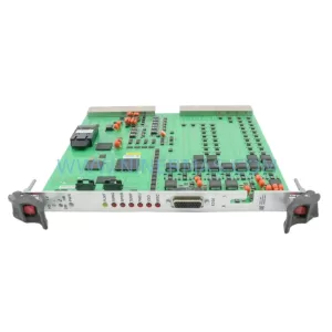
SKU: 4022.471.73662 0195-12261 UHG50-2B A4249-9215HG
ASML 4022.471.73662 Service-Ready Spare Part for Industrial Maintenance
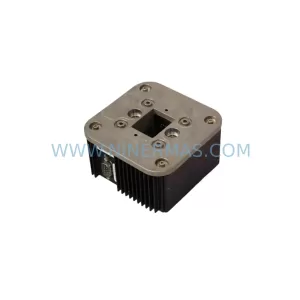
SKU: 4022.436.1723 112052-8 HEATER TI-XZ 0200-36543 BLM-013468
ASML 4022-436-1723-112052-8 Retrofit Heater for Legacy Systems
Catalog Continuation
Alternative parts within PLC & Industrial Automation Modules.
Stay inside the same system family when you need substitutes, adjacent modules, or a broader shortlist for procurement review.
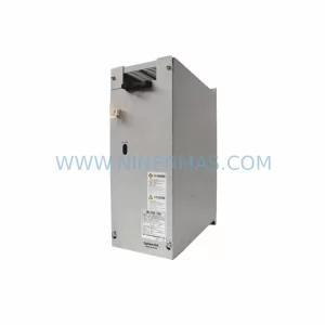
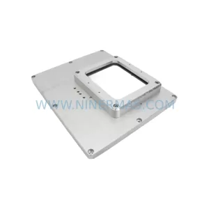
SKU: E17136671 E17268910 E17136671 E17268700 PSKF121 CMP50M/BP/KY/RH1M/SB1
Varian PSKF121-CMP50M-BP-KY-RH1M-SB1 Industrial Spare Part