Original Industrial Spare Part
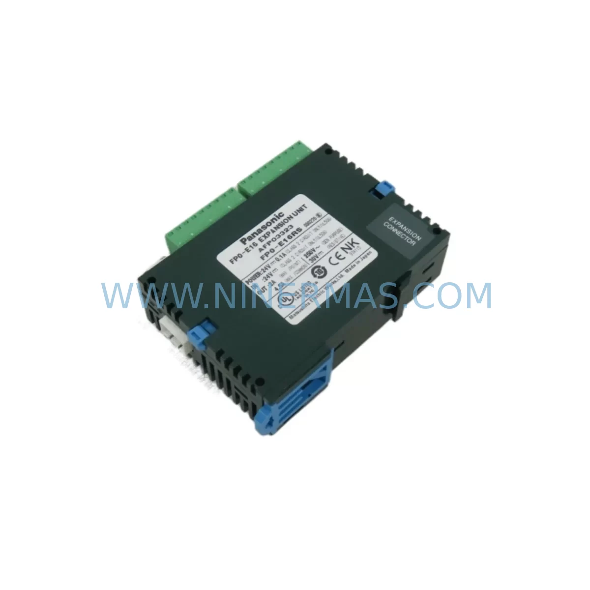
Panasonic FP0-E16 Retrofit I/O Expansion for Legacy Systems
Verify the part, confirm the platform family, and move straight into quotation with the right commercial details.
RFQ Ready
- SKUFPO-E16
- CategoryPLC & Industrial Automation Modules
- BrandPanasonic
- SupportAvailability, lead time, condition, and shipping coordination
How Buyers Usually Use This Page
- Confirm the exact part number and platform family before sending the quote request.
- Use direct email when quantity, condition, and destination are already defined internally.
- Switch to the broader brand or category archive when you need alternates nearby.
Series Navigation
Move through the most common platform families behind this part.
Product RFQ
Send this part directly for quotation.
Include quantity, required condition, destination country, and target delivery timing. Current reference: Panasonic FP0-E16 Retrofit I/O Expansion for Legacy Systems with SKU FPO-E16.
Panasonic FP0-E16 Retrofit I/O Expansion for Legacy Systems
The Panasonic FP0-E16 is a 16-point I/O expansion unit engineered for the FP0 compact PLC platform — one of Panasonic’s most widely deployed control architectures in small-to-medium automation systems. As the FP0 series approaches end-of-life status in many production environments, the FP0-E16 remains a critical retrofit component for engineers tasked with extending the operational lifespan of existing control panels, upgrading I/O capacity without replacing the entire PLC backbone, or restoring failed expansion modules in legacy lines where downtime carries significant cost.
For maintenance engineers and system integrators managing aging automation infrastructure, the FP0-E16 provides a direct-fit replacement path that preserves existing wiring, terminal layouts, and program logic. Its compact DIN-rail form factor and native compatibility with the FP0 CPU backplane make it the preferred choice when the goal is a controlled, low-risk upgrade rather than a full system overhaul.
Upgrade Compatibility Table
| Parameter | FP0-E16 Specification | Retrofit Notes |
|---|---|---|
| I/O Points | 16 points (8 IN / 8 OUT) | Verify I/O address allocation in CPU program before swap |
| Output Type | Transistor (NPN sink) | Confirm load polarity matches field devices |
| Supply Voltage | 24 VDC (from CPU or external) | Check FP0-PSA2 power supply capacity before adding expansion |
| Backplane Interface | FP0 proprietary expansion connector | Use AFP0523 expansion cable for remote mounting configurations |
| Module Address | Set via DIP switch on unit | Match address to original module; verify in FPWIN Pro program |
| Communication Protocol | Internal FP0 bus (not fieldbus) | No protocol migration required for local I/O replacement |
| Installation Space | 25mm width, DIN-rail mount | Confirm cabinet rail space; adjacent modules may need repositioning |
| Replacement Compatibility | Direct drop-in for FP0-E16 units | No program modification required if address unchanged |
| Pre-Shipment Testing | Full functional test performed | Each unit tested before dispatch |
| Warranty | 12-Month Warranty | Covers manufacturing defects and functional failure under normal use |
Retrofit Planning for Existing Automation Systems
Successful integration of the FP0-E16 into an existing control system begins well before the module arrives on-site. Engineers should start by auditing the current FP0 CPU — whether a FP0-C32CT, FP0-C16T, or similar variant — to confirm the total I/O count, available expansion slots, and current DIP switch addressing scheme. The FP0 platform supports a limited number of expansion units per CPU, so verifying the expansion chain before ordering prevents address conflicts and bus overload.
Power budget is a frequent oversight in retrofit projects. The FP0-PSA2 power supply unit has a defined output capacity, and adding or replacing an FP0-E16 expansion module increases the current draw on the 24 VDC rail. Before installation, calculate the combined load of all connected modules — including any FP0-E32T 32-point expansion units, FP0-A21 analog I/O units, or FP0-TC4 thermocouple input modules already in the rack — and confirm the supply margin is adequate. If the existing power supply is already near capacity, a supplementary 24 VDC source may be required.
Terminal wiring is the most time-sensitive task during a module swap. Document all field wiring connections on the original FP0-E16 before removal, including wire labels, terminal numbers, and signal types. The FP0-E16 uses a removable terminal block design on compatible configurations, which can simplify re-termination. For systems where the FP0-RTD6 RTD temperature input unit or FP0-TC4 thermocouple module feeds signals into the same control loop, ensure that the I/O address map in the FPWIN Pro or FPWIN GR programming environment reflects the correct module position after reinstallation.
If the retrofit involves remote mounting of the expansion unit — for example, when the FP0-E16 is installed in a satellite junction box away from the main CPU — the AFP0523 expansion cable provides the necessary backplane extension. Confirm cable length and routing before finalizing the panel layout. For programming access during commissioning, the AFP8550 USB programming cable connects the FP0 CPU to a laptop running FPWIN Pro, enabling live monitoring of I/O status, force-on/off testing of individual points, and program upload/download without interrupting the control loop.
Downtime Control During System Migration
Minimizing production downtime during an FP0-E16 replacement requires a structured pre-outage preparation protocol. Before the scheduled maintenance window, upload and archive the current PLC program from the FP0 CPU using FPWIN Pro. Store the program file with version control notation — including the date, machine ID, and technician name — so that the original logic can be restored immediately if the replacement module exhibits unexpected behavior during commissioning.
During the outage, follow a defined sequence: isolate the control panel from field power, photograph the existing wiring layout, remove the failed FP0-E16, install the replacement unit with the DIP switch address pre-set to match the original, re-terminate field wiring using the documented layout, and restore power in stages — first the CPU, then the expansion chain, then field devices. This staged power-up sequence allows the engineer to verify each subsystem before exposing field actuators to control signals.
After power restoration, use FPWIN Pro to monitor the I/O status display in real time. Force-test each input and output point on the new FP0-E16 before releasing the machine to production. For systems where the FP0-E16 controls safety-critical outputs — such as motor contactors, solenoid valves, or alarm relays — perform a full functional test of the associated control logic before resuming normal operation. Document the commissioning results and retain them with the maintenance record for the machine.
For sites with strict uptime requirements, consider maintaining a pre-configured spare FP0-E16 with the correct DIP switch settings and a printed wiring diagram attached. This reduces the active repair window to under 30 minutes in most panel configurations.
Retrofit Support FAQ
Q1: Is the FP0-E16 a direct replacement for a failed expansion module in my existing FP0 system?
Yes. The FP0-E16 is a direct drop-in replacement for units of the same model. Provided the DIP switch address is set to match the original module and field wiring is re-terminated correctly, no program modification is required. The FP0 CPU will recognize the replacement module at the same I/O address without requiring a program download.
Q2: What pre-shipment testing is performed on the FP0-E16 before dispatch?
Each FP0-E16 unit undergoes a full functional test prior to shipment, including power-on verification, I/O point actuation testing, and backplane interface check. Units that do not pass functional testing are not dispatched. A 12-month warranty covers manufacturing defects and functional failure under normal operating conditions from the date of delivery.
Q3: How do I confirm the correct DIP switch address setting before installing the replacement module?
Open the existing PLC program in FPWIN Pro and review the I/O allocation table. The address assigned to the original FP0-E16 will be listed as a specific unit number in the expansion chain. Set the DIP switches on the replacement module to match this unit number before installation. If the original module is still partially functional, photograph the DIP switch position before removal.
Q4: What is the lead time and stock availability for the FP0-E16?
The FP0-E16 is maintained in ready stock for immediate dispatch. Standard lead time for in-stock units is 1–3 business days for international shipments. For urgent requirements or bulk orders, contact our sales team directly to confirm availability and arrange priority dispatch. Long-term supply agreements and reserved inventory arrangements are available for sites with recurring maintenance needs.
| Product Series | Legacy |
|---|
Catalog Continuation
More Panasonic modules in the catalog.
Use the brand lane to compare nearby part numbers, platform-adjacent modules, and other inquiry-ready listings before sending your final RFQ.

SKU: ZUEP5585D 0.17KW MG_03_40_60 00-201-179 cloos pcif 033.59.20.00
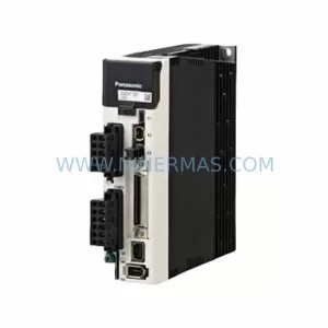
Panasonic ZUEP5585D Retrofit Servo Drive for Legacy Systems
SKU: MT-9-5.4-002LB MQMA022P2B 0150-76217 0100-01907 0100-20458
Panasonic MQMA022P2B Retrofit Servo Motor for Legacy Systems
Catalog Continuation
Alternative parts within PLC & Industrial Automation Modules.
Stay inside the same system family when you need substitutes, adjacent modules, or a broader shortlist for procurement review.
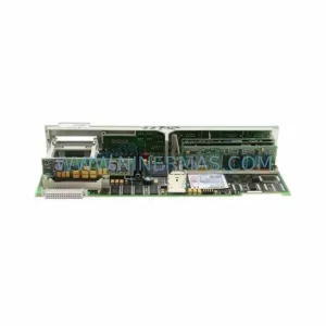
SKU: 6FC5357-0BB12-0AE0
Siemens 6FC5357-0BB12-0AE0 Service-Ready Industrial Spare Part
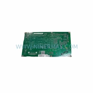
SKU: 3BSE011790R1(PXHK401)
ABB 3BSE011790R1 PXHK401 Retrofit-Ready Communication Module