Original Industrial Spare Part
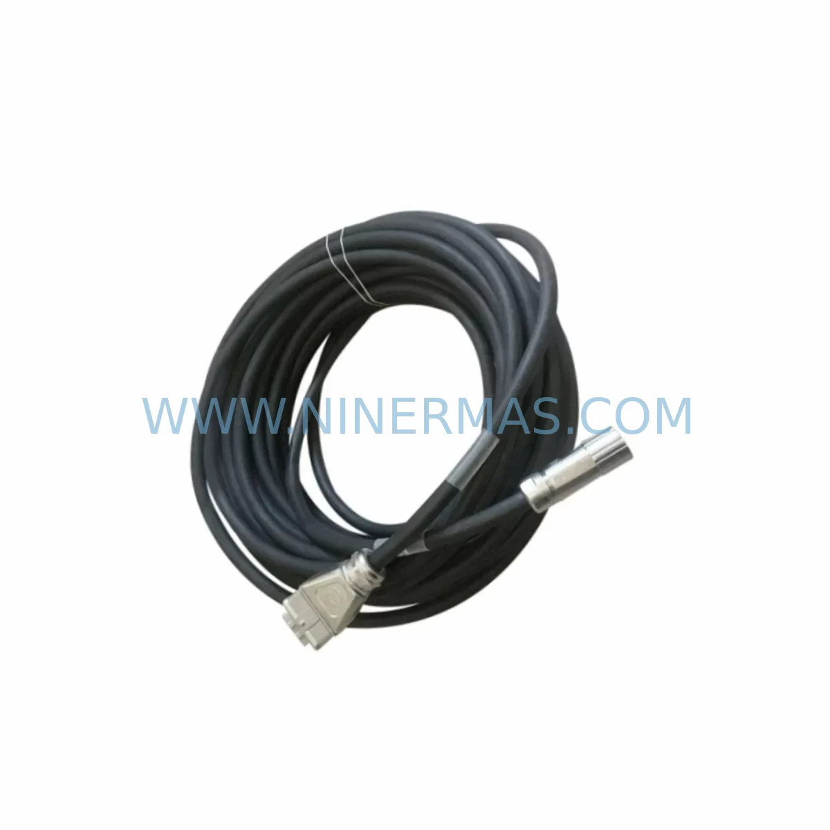
KUKA KR6 00-204-935 00-204-551 Retrofit-Compatible Signal Cable for Legacy Systems
Verify the part, confirm the platform family, and move straight into quotation with the right commercial details.
RFQ Ready
- SKUKR6 00-204-935 00-204-551
- CategoryPLC & Industrial Automation Modules
- BrandKUKA
- SupportAvailability, lead time, condition, and shipping coordination
How Buyers Usually Use This Page
- Confirm the exact part number and platform family before sending the quote request.
- Use direct email when quantity, condition, and destination are already defined internally.
- Switch to the broader brand or category archive when you need alternates nearby.
Series Navigation
Move through the most common platform families behind this part.
Product RFQ
Send this part directly for quotation.
Include quantity, required condition, destination country, and target delivery timing. Current reference: KUKA KR6 00-204-935 00-204-551 Retrofit-Compatible Signal Cable for Legacy Systems with SKU KR6 00-204-935 00-204-551.
KUKA KR6 00-204-935 00-204-551 Retrofit-Compatible Signal Cable for Legacy Systems
The KUKA KR6 00-204-935 / 00-204-551 is a ruggedized signal cable module engineered for demanding industrial environments and designed to serve as a direct retrofit replacement within aging KUKA KR6 robot controller architectures. As production lines built around the KUKA KR6 series approach end-of-life support cycles, maintenance engineers and automation integrators face increasing pressure to source compatible signal cable assemblies that preserve existing wiring harness layouts, connector pinouts, and signal integrity standards — without triggering a full controller overhaul.
NINERMAS maintains verified stock of the KR6 00-204-935 / 00-204-551 signal cable module, sourced from qualified industrial supply channels and subject to outgoing inspection prior to shipment. Each unit is covered by a 12-month warranty against manufacturing defects, giving procurement and maintenance teams the confidence to plan scheduled replacements and emergency restocks alike.
Upgrade Compatibility Table
| Parameter | Details |
|---|---|
| Part Numbers | 00-204-935 / 00-204-551 |
| Compatible Platform | KUKA KR6 Robot Series |
| Controller Compatibility | KRC1, KRC2 (legacy), KRC4 (verify harness adapter) |
| Connector Interface | Multi-pin ruggedized industrial connector; verify mating connector on existing harness before installation |
| Installation Space | Routed along robot arm cable management channel; confirm bend radius and cable tray clearance |
| Communication Compatibility | Analog/digital signal transmission; compatible with standard KUKA signal routing architecture |
| Replacement Recommendation | Direct drop-in for worn, damaged, or end-of-life OEM cable assemblies in KR6 installations |
| Commissioning Notes | Verify signal continuity after installation; re-run KUKA mastering procedure if axis feedback is affected |
| Warranty | 12 months from date of shipment |
Retrofit Planning for Existing Automation Systems
When planning a cable replacement or partial retrofit within a KUKA KR6 cell, the signal cable assembly is rarely the only component under review. A thorough retrofit assessment typically begins at the KRC2 or KRC4 controller cabinet, where the power supply module, safety interface board, and axis computer must all be confirmed operational before a cable swap is deemed sufficient. In many legacy installations, the KUKA KPS 600 power supply or its equivalent has already been flagged for replacement alongside the signal harness, since degraded power delivery can mask or amplify signal faults that appear to originate in the cable.
At the robot arm level, the 00-204-935 / 00-204-551 cable interfaces with the resolver feedback system and motor brake circuits. Engineers should inspect the KUKA motor connector housing and associated terminal blocks at the base of the robot for corrosion or mechanical wear before installing the new cable. If the installation involves a KRC2 controller, the DSE-IBS or DSE-RDW resolver digitizing board should be tested for signal acceptance after the new cable is seated, as these boards are sensitive to impedance changes introduced by non-OEM cable assemblies.
For cells that have been upgraded to KRC4 architecture, the signal cable routing may require an adapter harness or a revised cable management bracket, particularly if the original KR6 arm was installed under KRC1 or KRC2 specifications. In these mixed-generation environments, the KUKA CCU (Cabinet Control Unit) and KPP (KUKA Power Pack) modules should be verified for firmware compatibility with the updated signal path. The KUKA smartPAD teach pendant connection should also be checked, as HMI screen calibration and axis status displays can reflect signal anomalies during the transition period.
I/O expansion modules installed in the controller cabinet — such as Beckhoff EtherCAT I/O terminals or KUKA-compatible Profibus DP slave modules — should be mapped and documented before the cable replacement begins. Any changes to signal routing that affect I/O addressing must be reflected in the robot program and, where applicable, in the PLC logic controlling the cell. Signal isolators installed between the robot controller and external safety PLCs should be tested for correct threshold levels after the new cable is commissioned.
Where the retrofit involves communication protocol migration — for example, transitioning from DeviceNet to PROFINET or integrating the KR6 cell into an EtherNet/IP network — the signal cable replacement is an opportune moment to audit the full communication chain from the robot controller to the SCADA or MES layer. Programming cables such as the KUKA KLI Ethernet interface cable should be verified for compatibility with the updated network topology before the cell is returned to production.
Downtime Control During System Migration
Minimizing unplanned downtime during a signal cable replacement in a KUKA KR6 cell requires a structured pre-shutdown checklist and a clear rollback plan. Before the robot is powered down, the current robot program — including all taught positions, I/O assignments, and safety zone configurations — should be backed up to an external USB drive or network share using the KUKA KRC backup utility. This ensures that if the cable replacement introduces unexpected signal behavior, the original program logic can be restored without re-teaching the robot from scratch.
The physical replacement itself should be scheduled during a planned maintenance window, ideally aligned with a shift changeover or scheduled production break. A pre-staged replacement cable — verified against the part numbers 00-204-935 and 00-204-551 — should be on-site before the shutdown begins, eliminating the risk of extended downtime caused by last-minute sourcing delays. NINERMAS ships verified stock with outgoing inspection documentation, supporting just-in-time maintenance planning.
After the new cable is installed and routed through the existing cable management channel, the robot should be powered up in a controlled sequence: controller cabinet first, followed by the robot arm enable signal. The KUKA KRC diagnostic interface should be used to confirm that all axis resolver signals are within specification before the robot is moved under program control. If any axis reports a mastering error or resolver fault, the mastering procedure should be repeated using the KUKA Electronic Mastering Device (EMD) before the cell is returned to automatic mode.
Field continuity testing using a calibrated cable tester should be performed on the new assembly before installation to confirm that all signal conductors and shield connections are intact. This step, combined with the outgoing inspection performed by NINERMAS prior to shipment, provides two independent verification points that reduce the risk of a repeat failure and protect the integrity of the existing control system during the transition.
Retrofit Support FAQ
Q1: Is the KUKA KR6 00-204-935 / 00-204-551 a direct replacement for the original OEM cable assembly?
A: Yes. The 00-204-935 and 00-204-551 are the OEM part numbers for this signal cable assembly. Units supplied by NINERMAS are sourced from qualified industrial channels and verified against these part numbers prior to shipment. Customers should confirm the mating connector condition on the existing harness before installation.
Q2: What commissioning steps are required after installing the new signal cable?
A: After installation, perform a signal continuity check, power up the controller in sequence, and verify all axis resolver signals via the KRC diagnostic interface. If any mastering errors are reported, repeat the KUKA mastering procedure using the EMD. Re-validate I/O assignments and safety zone configurations before returning the cell to automatic mode.
Q3: Can this cable be used in a KRC4 controller environment originally designed for KRC2?
A: In mixed-generation environments, an adapter harness or revised cable management bracket may be required. Customers should verify the connector interface and cable routing path against the KRC4 cabinet layout before ordering. NINERMAS technical support can assist with compatibility verification based on your controller serial number and installation drawings.
Q4: What is the warranty and lead time for this part?
A: NINERMAS provides a 12-month warranty from the date of shipment against manufacturing defects. Stock availability is maintained for immediate dispatch. Lead time for in-stock units is typically 3–7 business days depending on destination. Contact our team for urgent or bulk order requirements.
| Product Series | Legacy |
|---|---|
| Country of Origin | DE |
Catalog Continuation
More KUKA modules in the catalog.
Use the brand lane to compare nearby part numbers, platform-adjacent modules, and other inquiry-ready listings before sending your final RFQ.
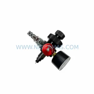
SKU: 00-207-218 C4 GA12
KUKA 00-207-218 GA12 Retrofit Drive for Legacy Systems
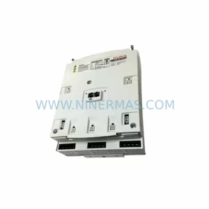
SKU: KPP 600-20 2X40 :00-160-152 KPP 600-20 3X20 UL :00-245-213 KPP 600-20 UL :00-198-259
KUKA KPP-600-20 Retrofit Power Supply for Legacy Systems
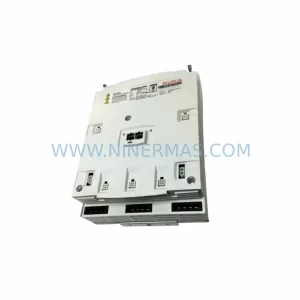
SKU: 00-106-446kr150.kr180 ZH150/180
KUKA 00-106-446 Retrofit-Compatible Gearbox for Legacy Systems
Catalog Continuation
Alternative parts within PLC & Industrial Automation Modules.
Stay inside the same system family when you need substitutes, adjacent modules, or a broader shortlist for procurement review.
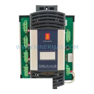
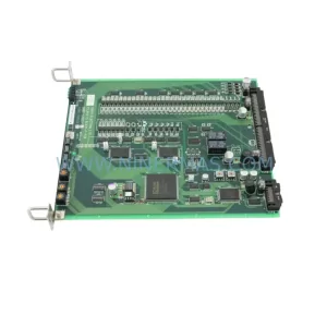
SKU: TTLM10-11 ELVIF-F 3895-120321-21 TTLD14-12 WCIF-L 3881-020032-11 TTLM11-11 W/TIF-L 3895-120322-21
TEL 3895-120321-21 Service-Ready Spare for Industrial Maintenance