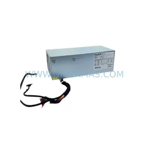
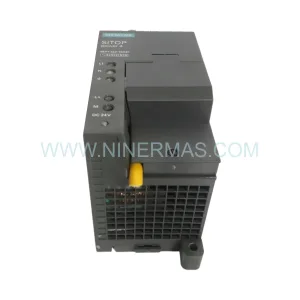
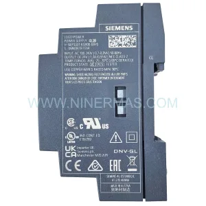
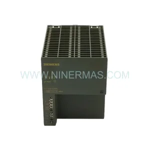
Original Industrial Spare Part
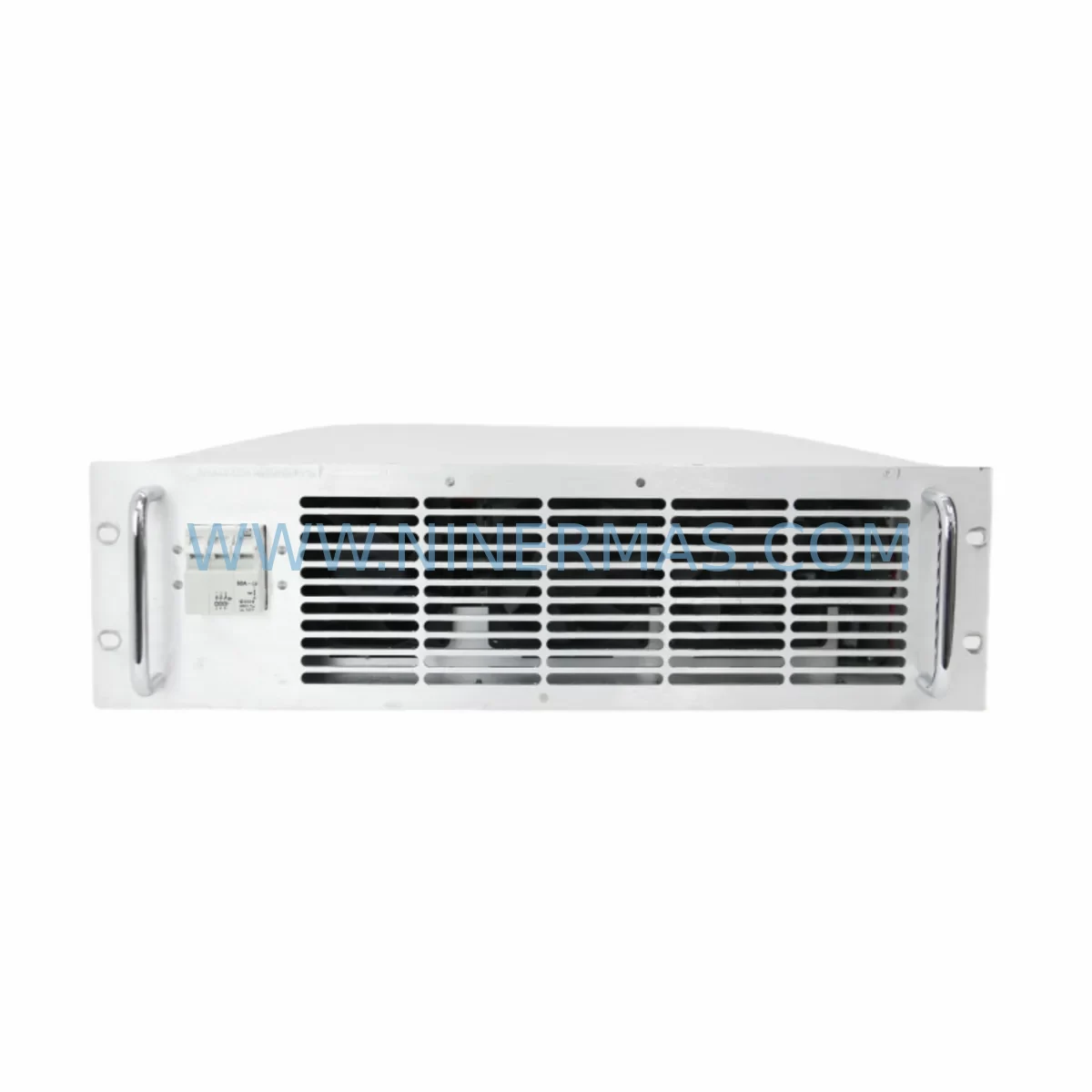
Lumina Power LPS-10000-250-40 Retrofit PSU for Legacy Systems
Verify the part, confirm the platform family, and move straight into quotation with the right commercial details.
RFQ Ready
- SKU11001381 LPS-10000-250-40 EX9699545 715-11005-001
- CategoryPLC & Industrial Automation Modules
- BrandLumina Power
- SupportAvailability, lead time, condition, and shipping coordination
How Buyers Usually Use This Page
- Confirm the exact part number and platform family before sending the quote request.
- Use direct email when quantity, condition, and destination are already defined internally.
- Switch to the broader brand or category archive when you need alternates nearby.
Series Navigation
Move through the most common platform families behind this part.
Product RFQ
Send this part directly for quotation.
Include quantity, required condition, destination country, and target delivery timing. Current reference: Lumina Power LPS-10000-250-40 Retrofit PSU for Legacy Systems with SKU 11001381 LPS-10000-250-40 EX9699545 715-11005-001.
Lumina Power LPS-10000-250-40 Retrofit PSU for Legacy Systems
The Lumina Power LPS-10000-250-40 is a ruggedized, high-reliability power supply engineered for demanding industrial environments. As legacy automation systems age and original equipment manufacturers discontinue support for older power modules, the LPS-10000-250-40 has become a critical retrofit and replacement component for facilities seeking to extend the operational life of their existing control infrastructure without committing to a full platform migration. With a rated output of 250 VDC at 40 A, this unit is designed to deliver stable, conditioned power to legacy control cabinets, distributed I/O racks, and safety-critical automation panels where power quality directly affects system reliability and uptime.
Industrial facilities operating legacy programmable logic controller platforms, distributed control systems, and older SCADA-integrated panels frequently encounter the challenge of sourcing compatible power supplies when original units fail or reach end-of-life. The LPS-10000-250-40 addresses this challenge directly by maintaining dimensional compatibility with standard 19-inch rack enclosures and offering terminal block configurations that align with legacy wiring practices, reducing the need for extensive rewiring during replacement. Each unit undergoes pre-shipment functional testing under load conditions to verify output voltage stability, ripple performance, and thermal behavior before dispatch, ensuring that field installation proceeds without unexpected commissioning delays.
Upgrade Compatibility Table
| Parameter | LPS-10000-250-40 (Replacement) | Typical Legacy Unit | Notes |
|---|---|---|---|
| Output Voltage | 250 VDC | 240–260 VDC (varies) | Verify load regulation tolerance with existing PLC backplane |
| Output Current | 40 A continuous | 35–42 A (model-dependent) | Confirm total rack current draw before installation |
| Input Voltage Range | 85–264 VAC, universal | Fixed 110/220 VAC | Universal input simplifies site adaptation |
| Mounting Format | 19-inch rack, 2U | 19-inch rack, 2U | Direct mechanical fit in most legacy enclosures |
| Terminal Block | Screw-type, M4 | Screw-type, M4/M5 | Verify torque spec; adapter lugs may be required for M5 legacy terminals |
| Communication Interface | RS-485 status output (optional) | Relay contact / analog signal | Map status signals to existing HMI or SCADA alarm inputs |
| Cooling Method | Forced air, front-to-rear | Forced air / convection | Confirm cabinet airflow direction before installation |
| Protection Features | OVP, OCP, OTP, SCP | OVP, OCP (basic) | Enhanced protection reduces nuisance trips in retrofit applications |
| Warranty | 12 Months | N/A (discontinued) | 12-month warranty covers parts and labor from date of shipment |
| Pre-Shipment Test | Full load burn-in | N/A | Test report available upon request |
Retrofit Planning for Existing Automation Systems
Successful integration of the LPS-10000-250-40 into an existing automation system requires a structured pre-installation assessment that addresses power budgeting, physical fit, wiring compatibility, and downstream device behavior. Before removing the legacy power supply, engineers should document the total current consumption of all modules installed in the control rack, including any Lumina Power LPS-5000-125-40 auxiliary supply units, I/O expansion modules, and communication adapters drawing power from the same bus. This baseline measurement ensures that the replacement unit’s 40 A output capacity is not exceeded under peak load conditions, particularly during system startup when inrush currents from motor drives and relay coils can momentarily spike demand.
Terminal block wiring should be photographed and labeled before disconnection. Legacy installations frequently use color-coded wiring schemes that do not conform to current IEC standards, and maintaining accurate records prevents miswiring during reinstallation. Where the existing cabinet uses M5 terminal lugs and the LPS-10000-250-40 ships with M4 terminals, appropriately rated adapter lugs must be sourced and installed to maintain connection integrity and comply with local electrical codes.
For systems that include a Lumina Power BP-400 backplane or equivalent passive distribution bus, verify that the backplane’s voltage rating and current capacity are compatible with the replacement unit’s output specifications. Backplanes in older installations may have derating requirements that are not documented in the original system drawings, particularly if the cabinet has been modified over time to accommodate additional I/O modules or communication cards.
Communication module integration is another area requiring careful attention. If the existing system uses a CM-485 serial communication module or a similar RS-485 interface card to relay power supply status to a supervisory SCADA system, the LPS-10000-250-40’s optional RS-485 status output can be configured to transmit alarm and status data in a format compatible with Modbus RTU polling. This eliminates the need to modify the SCADA polling logic or HMI alarm pages, preserving the original program logic and reducing commissioning time. Where the legacy system used relay contact outputs for alarm signaling, a signal isolator such as the SI-4020 can be used to convert the RS-485 status signal to a dry contact output compatible with existing alarm wiring.
HMI panels connected to the control system, such as the HP-700 operator interface, should be reviewed to confirm that power supply alarm tags are correctly mapped and that any changes to the alarm signal format are reflected in the HMI configuration. In many retrofit projects, HMI alarm pages reference legacy tag names that must be preserved to avoid retraining operators or modifying validated process documentation.
For facilities that also need to upgrade I/O capacity during the same maintenance window, the IOM-16DI digital input module is a compatible expansion option that can be installed in the same rack without requiring additional power supply capacity, provided the total rack current budget remains within the LPS-10000-250-40’s rated output. Programming cable PC-USB-LPS is recommended for firmware verification and configuration backup before and after the power supply replacement, ensuring that any embedded configuration parameters are preserved across the maintenance event. Rack mount hardware RM-19 should be inspected and replaced if corrosion or mechanical wear is present, as loose rack mounting can introduce vibration-induced connector failures in high-cycle industrial environments.
Downtime Control During System Migration
Minimizing unplanned downtime during a power supply replacement is a primary concern for facilities operating continuous processes where even brief interruptions carry significant production or safety consequences. A structured migration plan for the LPS-10000-250-40 retrofit should begin with a scheduled maintenance window that allows sufficient time for pre-installation verification, physical replacement, wiring reconnection, and functional testing before the system is returned to service.
Prior to beginning the physical replacement, a complete backup of the PLC program, HMI configuration, and any embedded parameters stored in communication modules should be performed using the appropriate programming cable and software. This backup protects against data loss in the event that a downstream device loses power unexpectedly during the replacement process. Where the control system supports hot-standby or redundant power configurations, the redundant supply should be verified as operational before the primary unit is removed, ensuring that the process remains under control throughout the maintenance activity.
During the physical replacement, all field wiring should remain connected to the terminal blocks where possible, with only the power supply’s output terminals disconnected to isolate the unit from the load. This approach preserves the wiring configuration and reduces the risk of miswiring during reinstallation. After the LPS-10000-250-40 is installed and output terminals are reconnected, a controlled power-up sequence should be followed, bringing the supply online at reduced load before applying full rack current, allowing the unit’s soft-start circuitry to stabilize output voltage before downstream devices begin drawing current.
Post-installation verification should include measurement of output voltage at the load terminals, confirmation of alarm signal continuity to the SCADA or HMI system, and a review of the PLC program execution status to confirm that all I/O modules have resumed normal operation. A signed commissioning record documenting the pre- and post-replacement measurements, the technician’s name, and the date of installation provides a traceable quality record that supports the 12-month warranty claim process if a warranty event occurs during the coverage period.
Retrofit Support FAQ
Q: Is the LPS-10000-250-40 a direct drop-in replacement for discontinued Lumina Power LPS series units?
A: In most cases, yes. The LPS-10000-250-40 maintains the same 19-inch, 2U rack form factor and M4 screw terminal configuration as earlier LPS series units. Minor differences in terminal torque specifications and airflow direction should be verified against the existing cabinet layout before installation. A dimensional drawing and terminal wiring diagram are available upon request.
Q: What commissioning steps are required after installation?
A: After physical installation and wiring reconnection, verify output voltage at the load terminals under no-load and full-load conditions. Confirm that all alarm and status signals are correctly received by the SCADA or HMI system. Restore the PLC program from backup if required and verify normal I/O module operation. A full commissioning checklist is available from our technical support team.
Q: Does the unit ship with a pre-shipment test report?
A: Yes. Each LPS-10000-250-40 unit undergoes a full load burn-in test before shipment. A test report documenting output voltage, ripple, and thermal performance is available upon request and can be provided with the shipment documentation to support incoming inspection requirements.
Q: What does the 12-month warranty cover?
A: The 12-month warranty covers manufacturing defects in materials and workmanship from the date of shipment. It includes repair or replacement of the unit at no charge for defects that arise under normal operating conditions. Warranty claims should be initiated by contacting our sales team with the unit serial number and a description of the observed fault. Reserved inventory is maintained to support rapid warranty replacement and minimize production downtime for customers with critical spare parts requirements.
| Product Series | Legacy |
|---|
Catalog Continuation
Alternative parts within PLC & Industrial Automation Modules.
Stay inside the same system family when you need substitutes, adjacent modules, or a broader shortlist for procurement review.
SKU: OZDPROFI12MG12
Hirschmann OZDPROFI12MG12 Spare Part for Industrial Maintenance
SKU: 07025-0000-70-1-04
KONTRON 07025-0000-70-1-04 Service-Ready Spare Part