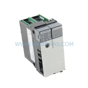
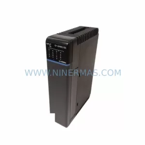
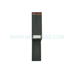
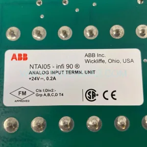
Original Industrial Spare Part
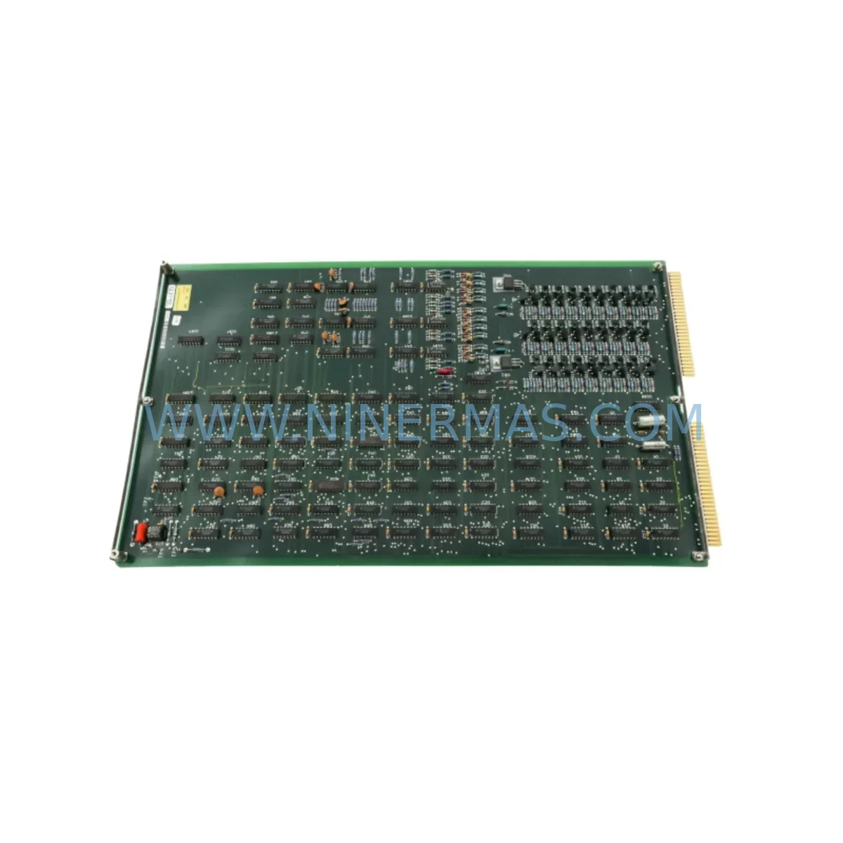
Teradyne 879-363-00 Service-Ready Spare Part for Industrial Maintenance
Verify the part, confirm the platform family, and move straight into quotation with the right commercial details.
RFQ Ready
- SKU810NM 879-363-00 AD363 15-118976-00 02-134263-00
- CategoryPLC & Industrial Automation Modules
- BrandTeradyne
- SupportAvailability, lead time, condition, and shipping coordination
How Buyers Usually Use This Page
- Confirm the exact part number and platform family before sending the quote request.
- Use direct email when quantity, condition, and destination are already defined internally.
- Switch to the broader brand or category archive when you need alternates nearby.
Series Navigation
Move through the most common platform families behind this part.
Product RFQ
Send this part directly for quotation.
Include quantity, required condition, destination country, and target delivery timing. Current reference: Teradyne 879-363-00 Service-Ready Spare Part for Industrial Maintenance with SKU 810NM 879-363-00 AD363 15-118976-00 02-134263-00.
Teradyne 879-363-00 Service-Ready Spare Part for Industrial Maintenance
The Teradyne 879-363-00 (also referenced as AD363, 15-118976-00, and 02-134263-00) is a ruggedized handler interface module engineered for deployment within Teradyne’s 810nm Automatic Test Equipment (ATE) platform. Designed to bridge the device handler and the test head in high-throughput semiconductor and electronics manufacturing environments, this module plays a mission-critical role in maintaining signal integrity, mechanical alignment, and electrical continuity between the handler and the tester. When this component fails or degrades, the entire test cell is at risk of unplanned downtime — making rapid, verified spare part availability a top priority for maintenance engineers and procurement teams alike.
At NINERMAS, every 879-363-00 unit is sourced from verified supply channels, subjected to pre-shipment functional inspection, and covered by a 12-month warranty. Our global inventory strategy ensures that service-ready stock is available for immediate dispatch, supporting both emergency replacement scenarios and planned annual maintenance cycles.
Spare Maintenance Table
| Part Number | 879-363-00 |
| Cross-Reference SKUs | AD363 / 15-118976-00 / 02-134263-00 |
| Brand | Teradyne |
| Series | 810nm ATE Platform |
| Product Type | Handler Interface Module |
| Form Factor | Ruggedized PCB Assembly with Interface Connector Array |
| Application | Semiconductor ATE Handler-to-Tester Interface, High-Volume Production Test |
| Operating Environment | Industrial / Harsh Environment (temperature-controlled test cell) |
| Signal Compatibility | Compatible with 810nm series test head interface and handler docking station |
| Condition | Original / Service-Ready (pre-shipment inspected) |
| Origin | USA (Teradyne Inc., North Reading, MA) |
| Warranty | 12 Months from date of shipment |
| Lead Time | Subject to stock availability — contact for confirmation |
| Maintenance Recommendation | Inspect connector pins and alignment guides every 6 months; replace upon signal integrity degradation or mechanical wear |
Maintenance Planning for Continuous Operation
Replacing the 879-363-00 handler interface module is rarely an isolated task. In a well-structured ATE maintenance program, this replacement serves as a trigger point for a broader inspection of the test cell’s electrical and mechanical ecosystem. Maintenance engineers who have worked with the 810nm platform understand that the handler interface module sits at the intersection of multiple subsystems — and that a failure here often signals stress or wear in adjacent components.
During a scheduled replacement of the 879-363-00, it is strongly recommended to simultaneously inspect the Teradyne 810nm power supply module that feeds the test head. Voltage instability or ripple from an aging power supply can accelerate connector wear on the interface module and lead to premature failure of the replacement unit. Similarly, the backplane signal distribution board within the test head chassis should be checked for oxidized contacts or cracked solder joints — a common finding in systems that have operated in thermally cycled environments for more than three years.
The DUT (Device Under Test) interface board and its associated precision cable assemblies connecting the handler to the test head should be visually inspected for insulation cracking, connector pin damage, and impedance drift. These cable assemblies, often part of the 810nm series interface kit, are subject to repeated mechanical stress from handler cycling and should be treated as consumable items in any serious spare parts inventory plan.
On the I/O side, the digital I/O interface card responsible for handler control signals — including bin sort outputs, end-of-test signals, and handler enable lines — should be verified for correct logic levels and response timing. A degraded I/O card can mask itself as a handler interface problem, leading to misdiagnosis and unnecessary module replacement. Alongside this, the relay board managing handler interlock and safety circuits deserves attention; relay contact resistance increases over time and can introduce false fault conditions that disrupt test cell throughput.
For sites running the 810nm platform in a networked test cell environment, the communication interface module — typically handling GPIB, LAN, or proprietary Teradyne bus protocols — should be confirmed as fully functional. Communication dropouts between the tester and the factory MES (Manufacturing Execution System) are a frequent source of phantom test failures that are incorrectly attributed to the handler interface. Additionally, the signal isolation board protecting sensitive analog measurement channels from handler-induced electrical noise should be tested for isolation resistance and leakage current, particularly in high-pin-count test configurations.
Finally, procurement engineers building a resilient spare parts kit for the 810nm platform should consider stocking the handler docking alignment guide assembly, thermal management fan tray, and fuse and circuit protection module alongside the 879-363-00. These components share the same replacement interval and are frequently needed together during annual overhaul cycles. Maintaining a minimum of one unit of each on the shelf eliminates the risk of extended downtime caused by a single unavailable part.
Site Replacement Workflow
Replacing the Teradyne 879-363-00 in the field follows a structured sequence designed to minimize test cell downtime and ensure system compatibility is preserved throughout the process.
Step 1 — Pre-Replacement Verification: Before removing the existing module, document the current system configuration, including handler model, test program version, and any site-specific interface adaptations. Confirm that the replacement 879-363-00 carries the correct revision level (cross-reference AD363, 15-118976-00, or 02-134263-00 as applicable to your system build). Mismatched revision levels between the interface module and the test head firmware can cause initialization failures that are difficult to diagnose without the original configuration record.
Step 2 — Safe Removal: Power down the test head and handler in the correct sequence per the 810nm platform safety procedure. Disconnect all cable assemblies from the interface module, labeling each connector position before removal. Inspect the vacated connector positions on the test head chassis for debris, bent pins, or corrosion before installing the replacement unit.
Step 3 — Installation and Alignment: Install the 879-363-00 replacement module, ensuring that the alignment guides engage correctly before applying mechanical fasteners. Over-torquing fasteners on ruggedized interface modules is a common cause of PCB stress fractures that manifest as intermittent failures weeks after installation. Follow the torque specification in the 810nm maintenance manual.
Step 4 — System Bring-Up and Validation: Power up the system and run the 810nm platform’s built-in self-test (BIST) sequence before loading any production test program. Verify that all handler control signals are correctly recognized by the tester and that the handler cycles through its full motion sequence without fault. Run a known-good device through the test program to confirm end-to-end signal integrity before returning the test cell to production.
Step 5 — Documentation: Record the replacement in the site maintenance log, including the new module’s serial number, installation date, and technician name. This record supports warranty claims and provides traceability for future maintenance planning.
Spare Parts Support FAQ
Q1: Is the 879-363-00 compatible with all revisions of the Teradyne 810nm platform?
The 879-363-00 is designed for the 810nm series test head interface. Compatibility with specific platform revisions depends on the firmware version and handler model in use at your site. NINERMAS recommends providing your system’s build configuration and handler model when placing an order so that our technical team can confirm revision-level compatibility before shipment. Cross-reference part numbers AD363, 15-118976-00, and 02-134263-00 are accepted for compatibility verification.
Q2: What pre-shipment testing does NINERMAS perform on the 879-363-00?
Every unit undergoes a multi-point inspection prior to shipment, including visual inspection of connector pins and PCB surfaces, continuity testing across all interface contacts, and functional verification where test equipment permits. Units that do not pass inspection are quarantined and not offered for sale. The 12-month warranty covers defects in materials and workmanship identified during normal use in the intended application environment.
Q3: Can NINERMAS support long-term supply agreements for the 879-363-00?
Yes. NINERMAS specializes in long-term supply of end-of-life and hard-to-source industrial automation spare parts. For customers with ongoing demand for the 879-363-00 or other 810nm platform components, we offer reserved inventory agreements that guarantee stock availability over a defined period. This is particularly valuable for manufacturing sites that cannot afford unplanned downtime due to spare part shortages. Contact our sales team to discuss volume and lead time requirements.
Q4: What is the recommended spare parts inventory strategy for the 810nm platform?
For a production test cell running the 810nm platform on a single-shift or multi-shift schedule, we recommend maintaining a minimum of two 879-363-00 units on-site: one as an active spare and one as a long-term reserve. Given the module’s role as a high-wear interface component, a replacement interval of 18–24 months is typical under normal production volumes. Annual maintenance cycles should include a condition assessment of the installed module, with replacement triggered by connector wear, signal integrity degradation, or mechanical damage — whichever occurs first.
| Product Series | Other series |
|---|
Catalog Continuation
More Teradyne modules in the catalog.
Use the brand lane to compare nearby part numbers, platform-adjacent modules, and other inquiry-ready listings before sending your final RFQ.
SKU: LA768 / 950-601-02 & 949-769-00/D 949-768-65 0040-18219 SE300
Teradyne LA768-950-601-02 Safety-Reliable Analog Input Module
Catalog Continuation
Alternative parts within PLC & Industrial Automation Modules.
Stay inside the same system family when you need substitutes, adjacent modules, or a broader shortlist for procurement review.
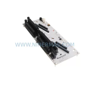
SKU: CC-TDOB11 51308373-175
HOLLEYWELL CC-TDOB11 51308373-175 Retrofit Digital Output
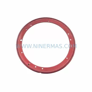
SKU: DIA 27CM 0020-21422 ARIES ACR CP*AR-13CE-15122 LAM 796-901039-002 100018066
AMAT 796-901039-002 Retrofit-Compatible Clamp for Legacy Systems