Original Industrial Spare Part
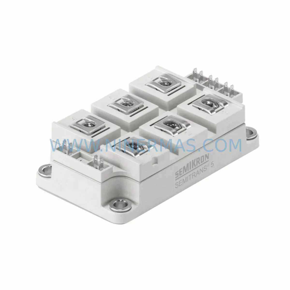
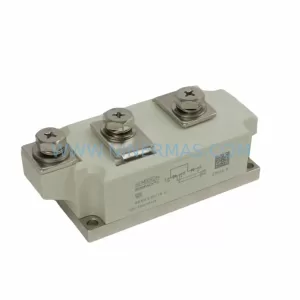
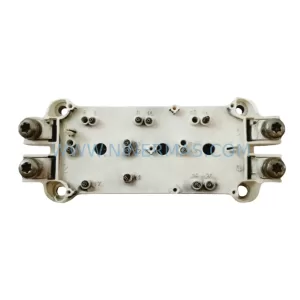
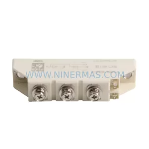
Semikron SKKR300/0.2-BVR Retrofit SCR Module for Legacy Systems
Verify the part, confirm the platform family, and move straight into quotation with the right commercial details.
RFQ Ready
- SKUSKKR300/0.2-BVR
- CategoryPLC & Industrial Automation Modules
- BrandSemikron
- SupportAvailability, lead time, condition, and shipping coordination
How Buyers Usually Use This Page
- Confirm the exact part number and platform family before sending the quote request.
- Use direct email when quantity, condition, and destination are already defined internally.
- Switch to the broader brand or category archive when you need alternates nearby.
Series Navigation
Move through the most common platform families behind this part.
Product RFQ
Send this part directly for quotation.
Include quantity, required condition, destination country, and target delivery timing. Current reference: Semikron SKKR300/0.2-BVR Retrofit SCR Module for Legacy Systems with SKU SKKR300/0.2-BVR.
Semikron SKKR300/0.2-BVR Retrofit SCR Module for Legacy Systems
The Semikron SKKR300/0.2-BVR is a high-current thyristor (SCR) rectifier module rated at 300 A average on-state current with a repetitive peak reverse voltage of 200 V. Designed for three-phase half-controlled and fully-controlled bridge rectifier topologies, this module has been widely deployed in legacy DC drive systems, industrial rectifier cabinets, electroplating lines, and crane hoist controllers manufactured throughout the 1990s and 2000s. As original equipment reaches end-of-life and OEM spare parts become increasingly scarce, the SKKR300/0.2-BVR remains one of the most sought-after retrofit-compatible SCR modules for plant engineers tasked with extending the operational life of existing automation infrastructure without committing to a full drive replacement.
Sourced from verified supply channels and subject to pre-shipment functional testing, each unit supplied by NINERMAS COMPANY LIMITED is accompanied by a 12-month warranty covering manufacturing defects and parametric conformance. Inventory is maintained to support urgent breakdown orders and planned maintenance windows alike, with typical lead times confirmed at order placement.
Upgrade Compatibility Table
| Parameter | SKKR300/0.2-BVR Specification | Retrofit / Replacement Notes |
|---|---|---|
| Average On-State Current (IT(AV)) | 300 A | Verify heat sink thermal resistance; derate if ambient >40 °C |
| Repetitive Peak Reverse Voltage (VRRM) | 200 V | Confirm AC supply voltage and transformer secondary; upgrade to SKKR300/04 (400 V) if margin is insufficient |
| Package / Mounting | SKKR flat-base module (Semikron standard) | Direct mechanical fit for existing SKKR300 footprint; verify torque spec (2.5–3.0 Nm) on mounting screws |
| Gate Trigger Current (IGT) | ≤150 mA (typ. 80 mA) | Compatible with standard SCR gate driver boards; no gate resistor change required in most legacy designs |
| Thermal Interface | Requires thermal compound (not included) | Clean heat sink surface; apply fresh thermal paste before installation |
| Communication / Control Interface | N/A (power module only) | Control signals remain at firing board level; no firmware or protocol changes required |
| Common Replacement Paths | SKKR300/0.2-BVR → SKKR300/0.2-BVR (like-for-like) or SKKR300/04 (voltage upgrade) | Cross-reference with Semikron SKKR series datasheet for pin-compatible alternatives |
| Warranty | 12 Months — covers manufacturing defects and parametric conformance from date of shipment | |
Retrofit Planning for Existing Automation Systems
When a legacy DC drive or rectifier cabinet experiences thyristor failure, the immediate priority is accurate fault isolation before ordering replacement modules. In many installations, the SKKR300/0.2-BVR operates alongside a Semikron SKKT330/16E or SKKT500/16E thyristor module in a parallel or complementary bridge configuration. Engineers should measure forward voltage drop across each thyristor leg and compare gate trigger response before concluding that the SKKR module alone is at fault.
Power supply integrity is the next checkpoint. Many legacy rectifier cabinets use a Siemens SITOP 6EP1336 or equivalent 24 VDC auxiliary power supply to feed the firing board and control logic. A degraded auxiliary supply can cause erratic gate triggering that mimics thyristor failure. Confirm auxiliary voltage under load before replacing the power module. Similarly, the firing board — often a Semikron SKHI 22A or a third-party equivalent — should be inspected for dry solder joints and capacitor aging, as these components share the same service life as the thyristor module itself.
Terminal wiring and busbar connections deserve careful attention during retrofit. The SKKR300/0.2-BVR uses M8 power terminals rated for the full 300 A continuous current. In older installations, copper busbars may have developed oxidation or micro-cracks at the terminal interface, increasing contact resistance and generating localised heat that accelerates thyristor degradation. Clean and re-torque all power connections to the manufacturer’s specification as part of the replacement procedure. Where the original wiring uses aluminium conductors, apply appropriate anti-oxidant compound before reassembly.
Backplane and rack compatibility is straightforward for like-for-like SKKR replacements, as the module footprint and mounting hole pattern are standardised across the SKKR series. However, if the retrofit involves migrating from an older SKKR160 or SKKR200 to the higher-rated SKKR300, verify that the existing heat sink surface area and cooling airflow are adequate for the increased thermal dissipation. In forced-air cooled cabinets, check that the fan unit — frequently a Semikron SKF 25 AC or equivalent — is operational and that filter mats are clean.
For systems where the original control architecture includes a Siemens SIMOREG DC Master 6RA70 or an older 6RA24 series converter, the thyristor module replacement does not require any parameter changes in the drive controller, provided the replacement module is electrically equivalent. The drive’s current controller and firing angle calculation remain valid. However, after module replacement, it is good practice to perform a current loop optimisation run and verify that the drive’s overcurrent trip threshold is correctly set relative to the new module’s surge current rating (ITSM).
I/O expansion and signal isolation should also be reviewed during planned retrofit windows. If the control cabinet includes a Pepperl+Fuchs or Phoenix Contact signal isolator feeding analogue setpoints to the firing board, verify isolation barrier integrity and recalibrate zero and span after the power module is replaced. Any drift in the analogue signal chain can cause speed or torque instability that is incorrectly attributed to the new thyristor module. Where the system uses a Profibus DP or Modbus RTU communication link to a PLC — such as a Siemens S7-300 with a CP 342-5 Profibus module — confirm that the communication link remains stable throughout the commissioning run and that no watchdog faults are generated during the initial load test.
Downtime Control During System Migration
Minimising production downtime during a thyristor module replacement requires a structured approach that begins well before the maintenance window opens. The first step is to obtain the replacement SKKR300/0.2-BVR module and verify its parameters against the original datasheet before the planned shutdown. Pre-shipment testing performed by NINERMAS confirms gate trigger voltage, forward voltage drop, and leakage current, but on-site incoming inspection using a thyristor tester or curve tracer provides an additional layer of confidence and eliminates the risk of discovering a defective unit after the original module has been removed.
Before de-energising the drive, capture a full snapshot of the control system state: record all drive parameters from the SIMOREG or equivalent controller, save the PLC programme from the S7-300 or similar CPU to an offline backup, and photograph the HMI screen layouts if the system uses a Siemens TP700 Comfort or equivalent panel. This documentation ensures that any inadvertent parameter loss during power cycling can be recovered quickly without extending the downtime window.
During the physical replacement, follow a strict lockout/tagout procedure and discharge DC bus capacitors fully before touching any power terminals. Replace the thermal interface material, re-torque all power connections, and perform a cold insulation resistance test between the power terminals and the heat sink before re-energising. Bring the system up at reduced load initially — typically 25–50% of rated current — and monitor module case temperature, gate waveforms, and output DC voltage ripple for at least 30 minutes before returning to full production load. This staged commissioning approach catches installation errors before they cause secondary damage and provides documented evidence that the retrofit was completed correctly.
Where a hot-standby or redundant drive configuration is available, coordinate the switchover so that production continues on the standby path while the primary drive is being serviced. Even in single-drive installations, pre-positioning a tested spare SKKR300/0.2-BVR module in the plant stores — supported by NINERMAS’s stocking programme — reduces the mean time to repair for future failures from days to hours.
Retrofit Support FAQ
Q1: Is the SKKR300/0.2-BVR a direct drop-in replacement for the original Semikron module of the same part number?
Yes. The SKKR300/0.2-BVR supplied by NINERMAS conforms to the original Semikron datasheet for package dimensions, terminal positions, and electrical parameters. No mechanical modification to the heat sink or busbar is required for a like-for-like replacement. Confirm the thermal interface compound is renewed and that mounting torque is applied to specification.
Q2: What commissioning checks are required after installation?
After mechanical installation and before energising, perform an insulation resistance test (500 VDC megger) between power terminals and the heat sink. On first energisation, verify gate trigger pulses on all thyristor gates using an oscilloscope, confirm DC output voltage at no-load, and check module case temperature at 50% and 100% rated load. Log all readings and compare against the pre-fault baseline if available.
Q3: Can the SKKR300/0.2-BVR be used to upgrade a system currently fitted with a lower-rated SKKR200 module?
The SKKR300 and SKKR200 share the same package footprint, making mechanical substitution straightforward. However, upgrading to a higher current rating requires verification that the heat sink, busbars, cabling, and upstream fusing are all rated for the higher continuous current. The firing board and gate driver circuit must also be confirmed compatible with the SKKR300’s gate trigger requirements. Consult the Semikron SKKR series application note before proceeding.
Q4: What warranty and supply terms does NINERMAS offer?
All SKKR300/0.2-BVR units supplied by NINERMAS COMPANY LIMITED carry a 12-month warranty from the date of shipment, covering manufacturing defects and parametric non-conformance. Pre-shipment functional testing is performed on every unit. Stock availability is confirmed at order placement, and lead time is communicated before invoice. For urgent breakdown orders, contact the sales team directly to confirm same-day or next-business-day despatch options.
| Product Series | Legacy |
|---|
Catalog Continuation
More Semikron modules in the catalog.
Use the brand lane to compare nearby part numbers, platform-adjacent modules, and other inquiry-ready listings before sending your final RFQ.
Catalog Continuation
Alternative parts within PLC & Industrial Automation Modules.
Stay inside the same system family when you need substitutes, adjacent modules, or a broader shortlist for procurement review.
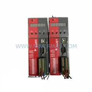
SKU: SC34.0300.0011.0000.0-JW1 SC34.0300.0011.0000.0
LUST SC34.0300.0011.0000.0-JW1 Service-Ready Spare Part
SKU: LSC-096-2-30-560-P5B0H2MM0
LTi Motion LSC-096-2-30-560-P5B0H2MM0 Retrofit Servo Drive
SKU: DS200SHVMG1AFE
GE DS200SHVMG1AFE Retrofit-Compatible Interface Module