Original Industrial Spare Part
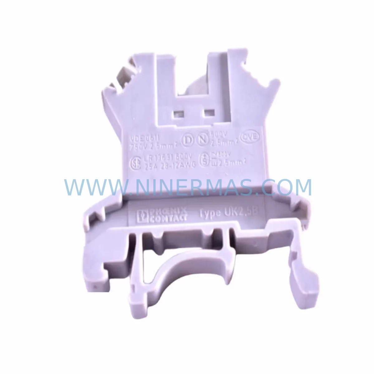
Phoenix Contact UK2.5B Retrofit-Compatible Terminal Block for Legacy Systems
Verify the part, confirm the platform family, and move straight into quotation with the right commercial details.
RFQ Ready
- SKUPHOENIX UK2.5B terminal block
- CategoryPLC & Industrial Automation Modules
- BrandPhoenix Contact
- SupportAvailability, lead time, condition, and shipping coordination
How Buyers Usually Use This Page
- Confirm the exact part number and platform family before sending the quote request.
- Use direct email when quantity, condition, and destination are already defined internally.
- Switch to the broader brand or category archive when you need alternates nearby.
Series Navigation
Move through the most common platform families behind this part.
Product RFQ
Send this part directly for quotation.
Include quantity, required condition, destination country, and target delivery timing. Current reference: Phoenix Contact UK2.5B Retrofit-Compatible Terminal Block for Legacy Systems with SKU PHOENIX UK2.5B terminal block.
Phoenix Contact UK2.5B Retrofit-Compatible Terminal Block for Legacy Systems
The Phoenix Contact UK2.5B is a proven, retrofit-compatible terminal block engineered for seamless integration into legacy control panel wiring systems. As industrial facilities face increasing pressure to modernize aging infrastructure without full system overhauls, the UK2.5B provides a reliable, drop-in compatible solution for control cabinet upgrades, field junction box rewiring, and I/O marshalling panel refurbishment. Whether you are replacing worn or discontinued UK 2.5 series blocks in an existing DIN rail assembly or expanding terminal capacity in a live production environment, the UK2.5B delivers the dimensional consistency, conductor compatibility, and clamping performance required for uninterrupted retrofit execution.
Designed to the IEC 60947-7-1 standard, the UK2.5B accepts conductors from 0.2 mm² to 4 mm² (AWG 24–12), making it directly compatible with the majority of field wiring gauges found in legacy process control and discrete manufacturing installations. The screw-clamp connection mechanism ensures repeatable torque performance across maintenance cycles, reducing the risk of loose terminations that commonly cause intermittent faults in aging control systems. The 6 mm pitch and standard DIN 35 rail mounting footprint allow direct substitution of older UK series blocks without requiring rail replacement or panel re-drilling — a critical advantage when downtime windows are measured in hours, not days.
Upgrade Compatibility Table
| Parameter | UK2.5B Specification | Retrofit Notes |
|---|---|---|
| Rated Voltage | 800 V AC/DC | Compatible with standard 24 VDC and 120/240 VAC control circuits |
| Rated Current | 24 A | Verify existing circuit load; suitable for most I/O and signal wiring |
| Conductor Range | 0.2–4 mm² (AWG 24–12) | Direct match for legacy field wiring; no re-termination gauge change required |
| Connection Type | Screw clamp | Compatible with existing screwdriver tooling; no special crimp tools needed |
| Mounting | DIN 35 rail (EN 60715) | Drop-in fit on existing rails; no panel modification required |
| Pitch | 6 mm | Matches UK series pitch; maintains existing terminal numbering layout |
| Communication Compatibility | Passive wiring terminal | Compatible with all signal types: analog, digital, thermocouple, RTD |
| Replacement Recommendation | Direct substitute for UK 2.5, UK 2.5 N, UK 2.5 B legacy variants | Confirm color coding and marker strip compatibility before bulk replacement |
| Commissioning Focus | Torque verification, continuity test, insulation resistance check | Use calibrated torque screwdriver; test each circuit before energizing |
| Warranty | 12 Months | Covers manufacturing defects; pre-shipment continuity and insulation tested |
Retrofit Planning for Existing Automation Systems
Successful integration of the UK2.5B into a legacy control system begins well before the first terminal block is removed from the DIN rail. Retrofit planning must account for the full wiring ecosystem within the control cabinet, including the power supply module feeding the terminal strip, the I/O modules connected downstream, and the communication interfaces linking field devices to the controller.
In a typical legacy PLC cabinet — for example, one built around a Siemens S5 or early S7-300 platform — the terminal strip serves as the marshalling point between field cables and the PLC’s I/O modules such as the SM 321 digital input module or SM 331 analog input module. When replacing the terminal blocks in such a cabinet, engineers must first document the existing wire labels, conductor colors, and circuit numbers using the original wiring diagram. If the original documentation is unavailable, a point-to-point continuity survey must be completed before any terminal is disturbed.
The UK2.5B’s 6 mm pitch and standard DIN 35 footprint mean that in most cases, the existing Phoenix Contact UK 2.5 or UK 2.5 N blocks can be replaced one-for-one without repositioning the rail or modifying the cable duct. However, engineers should verify that the adjacent end brackets, such as the Phoenix Contact D-UK 2.5 end bracket and the UK-QUATTRO grouping marker, remain compatible with the new block geometry. In installations where the terminal strip includes Phoenix Contact USLKG 2.5 grounding terminals or UK 5-TWIN double-level terminals, these should be retained in their original positions and only the standard feed-through blocks replaced with UK2.5B units.
For control cabinets that also house a Phoenix Contact QUINT-PS 24VDC power supply or similar DIN rail power supply module, the retrofit team should confirm that the power supply’s output current rating is sufficient to support the full terminal strip load after any I/O expansion. If the retrofit includes adding new I/O points — for example, connecting additional field sensors to a Weidmüller WDU 2.5 or equivalent terminal — the power budget must be recalculated before commissioning.
In installations where the terminal strip interfaces with a Phoenix Contact FL SWITCH managed Ethernet switch or a TRIO-PS power supply for network infrastructure, the signal wiring routed through the UK2.5B terminals must be verified for correct shielding and grounding practices. Improper shield termination at the terminal block level is a common source of EMI-induced faults in retrofitted systems, particularly in environments with variable frequency drives or high-current motor starters in the same cabinet.
Where the legacy system includes a Phoenix Contact RAD-ISM wireless I/O module or a PSI-MOS fiber optic modem for remote I/O communication, the terminal blocks connecting the module’s field-side wiring should be replaced as part of the same retrofit scope to ensure consistent connection quality across the communication link. Mixing aged and new terminal blocks within the same marshalling group increases the risk of differential contact resistance, which can cause signal drift in analog loops.
Downtime Control During System Migration
Minimizing production downtime during a terminal block retrofit requires a structured, zone-by-zone replacement strategy rather than a full cabinet shutdown. The recommended approach is to divide the terminal strip into functional groups — power distribution, digital I/O, analog signals, and communication wiring — and replace each group sequentially during planned maintenance windows.
Before beginning any terminal replacement, the original PLC program logic should be exported and backed up to an offline programming device. For Siemens S7 platforms, this means saving the complete project in STEP 7 or TIA Portal before any hardware changes are made. For Allen-Bradley systems, the RSLogix or Studio 5000 project file should be archived. This backup protects against accidental program loss if a controller reset occurs during the rewiring process.
During the replacement of each terminal group, the corresponding I/O module should be placed in a safe state — either by forcing outputs to a known safe condition in the PLC program or by physically isolating the module using the rack’s slot addressing. For systems using a Phoenix Contact IB IL 24 DI 16 Inline I/O module or similar distributed I/O node, the node can often be taken offline independently without shutting down the entire control network, allowing the rest of the system to continue operating during the terminal replacement.
After each terminal group is replaced with UK2.5B blocks, a point-to-point continuity test and insulation resistance measurement should be performed before reconnecting the I/O module. Insulation resistance between each conductor and the cabinet earth should exceed 1 MΩ at 500 VDC test voltage. Only after passing this test should the module be re-enabled and the PLC I/O forced values released. This sequential validation approach ensures that no single wiring error propagates into a system-wide fault, and that the total retrofit can be completed with the minimum number of full production stops.
For facilities operating continuous processes where even a brief shutdown is unacceptable, a parallel wiring strategy can be employed: new UK2.5B terminal strips are pre-wired on a spare DIN rail section alongside the existing terminal strip, and field cables are transferred one circuit at a time with immediate verification after each transfer. This approach extends the total retrofit duration but eliminates the need for any planned production stop.
Retrofit Support FAQ
Q1: Is the Phoenix Contact UK2.5B a direct replacement for the UK 2.5 and UK 2.5 N terminal blocks?
Yes. The UK2.5B shares the same 6 mm pitch, DIN 35 rail mounting, and conductor range as the UK 2.5 and UK 2.5 N series. It is dimensionally and electrically compatible for direct substitution in existing terminal strip assemblies. Confirm that your existing marker strips and end brackets are compatible before proceeding with bulk replacement.
Q2: What commissioning checks are required after replacing terminal blocks in a live control cabinet?
After replacement, perform a point-to-point continuity test on every circuit, an insulation resistance test at 500 VDC between each conductor and cabinet earth (minimum 1 MΩ), and a torque verification on each screw clamp using a calibrated torque screwdriver. Re-enable I/O modules sequentially and verify PLC I/O status in the programming software before releasing any forced values.
Q3: Can the UK2.5B be used with thermocouple and RTD signal wiring in analog input circuits?
Yes. The UK2.5B is a passive feed-through terminal and is compatible with all signal types including thermocouple, RTD, 4–20 mA analog, and 24 VDC digital signals. For thermocouple circuits, ensure that the wiring from the field device to the terminal block uses the correct thermocouple extension cable to avoid introducing a cold junction error at the terminal.
Q4: What is the warranty coverage and how are units tested before shipment?
All UK2.5B units supplied by NINERMAS carry a 12-month warranty covering manufacturing defects in materials and workmanship. Each batch undergoes pre-shipment continuity and insulation resistance testing. In-stock units are available for immediate dispatch, supporting urgent retrofit and emergency spare parts requirements. Contact our team for volume pricing and long-term supply program options.
| Product Series | Legacy |
|---|---|
| Country of Origin | DE |
Catalog Continuation
More Phoenix Contact modules in the catalog.
Use the brand lane to compare nearby part numbers, platform-adjacent modules, and other inquiry-ready listings before sending your final RFQ.
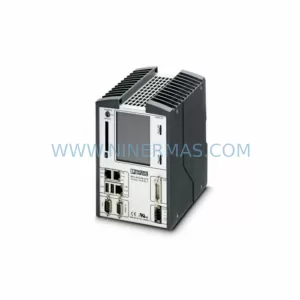
Catalog Continuation
Alternative parts within PLC & Industrial Automation Modules.
Stay inside the same system family when you need substitutes, adjacent modules, or a broader shortlist for procurement review.
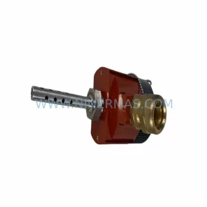
SKU: TRY/PRG/4-20MA/10-30DC
MOORE TRY/PRG/4-20MA/10-30DC Service-Ready Spare Part
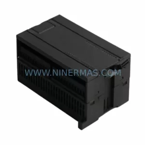
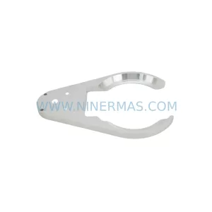
SKU: 5085-404901-11 12INCH 2910-202413-12 404200XRMPD2H14 7-249717
TEL 5085-404901-11 Service-Ready Spare Part for Industrial Maintenance
SKU: DIP011 05-058-011
SIGMATEK DIP011 05-058-011 Service-Ready Spare Part