Original Industrial Spare Part
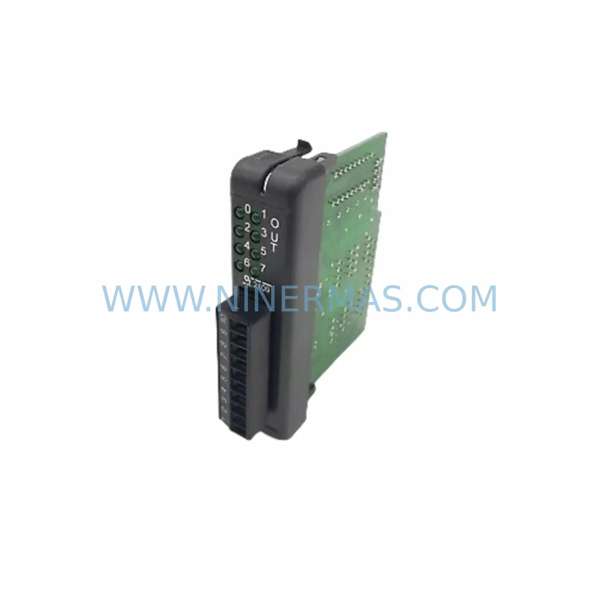
OPTILOGTC OL2109 Retrofit-Compatible Output Module for Legacy Systems
Verify the part, confirm the platform family, and move straight into quotation with the right commercial details.
RFQ Ready
- SKUOL2109
- CategoryPLC & Industrial Automation Modules
- BrandOPTILOGTC
- SupportAvailability, lead time, condition, and shipping coordination
How Buyers Usually Use This Page
- Confirm the exact part number and platform family before sending the quote request.
- Use direct email when quantity, condition, and destination are already defined internally.
- Switch to the broader brand or category archive when you need alternates nearby.
Series Navigation
Move through the most common platform families behind this part.
Product RFQ
Send this part directly for quotation.
Include quantity, required condition, destination country, and target delivery timing. Current reference: OPTILOGTC OL2109 Retrofit-Compatible Output Module for Legacy Systems with SKU OL2109.
OPTILOGTC OL2109 Retrofit-Compatible Output Module for Legacy Systems
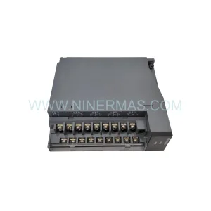
The OPTILOGTC OL2109 is a discrete output module engineered for seamless integration into legacy industrial automation environments. As production lines age and original equipment manufacturers discontinue support for older control platforms, the OL2109 provides a reliable, drop-in-compatible solution for facilities that need to extend the operational life of their existing control cabinets without committing to a full system overhaul. Whether you are managing a brownfield retrofit, replacing a failed output card in a running production cell, or planning a phased migration to a modern PLC architecture, the OL2109 delivers the signal integrity, load capacity, and backplane compatibility required to keep your process running.
NINERMAS COMPANY LIMITED maintains verified in-stock inventory of the OL2109 and ships with a 12-month warranty on all spare parts, giving procurement teams and maintenance engineers the confidence to plan long-term without exposure to supply chain risk.
Upgrade Compatibility Table
| Parameter | OL2109 Specification | Retrofit Notes |
|---|---|---|
| Module Type | Discrete Output Module | Replaces legacy relay or transistor output cards of equivalent channel count |
| Output Channels | 16-point (inferred from OL-series standard) | Verify channel mapping against original I/O address table before wiring |
| Backplane Interface | OPTILOGTC OL-series rack compatible | Confirm rack slot pitch and bus connector type; adapter plates may be required for third-party racks |
| Communication Compatibility | Parallel backplane bus | No protocol conversion required for same-series rack; Modbus RTU gateway may be needed for cross-platform integration |
| Power Supply Requirement | 24 VDC field power (typical) | Verify existing PSU capacity; add OPTILOGTC OL-series power supply module if load budget is exceeded |
| Terminal Wiring | Removable screw terminal block | Re-use existing field wiring where conductor gauge is compatible; re-label terminals per new I/O map |
| Installation Space | Standard single-slot module | Measure available rail space in control cabinet before ordering; DIN rail adapter available |
| Replacement Recommendation | Direct replacement for OL-series output cards | Cross-reference original part number against OPTILOGTC compatibility matrix |
| Commissioning Focus | I/O force test, output load verification | Use programming software to force each output point; confirm field device response before releasing to auto mode |
| Warranty | 12 Months | Covered by NINERMAS spare parts warranty program; DOA replacement within 30 days |
Retrofit Planning for Existing Automation Systems
Integrating the OPTILOGTC OL2109 into an existing control architecture requires a structured approach that accounts for every layer of the automation stack. Begin with a full audit of the control cabinet: document the existing rack configuration, identify the slot position of the output module being replaced, and photograph the terminal wiring before disconnecting any field cables. This step is critical when the original wiring documentation is incomplete or has drifted from the as-built state.
Power budget verification is the next priority. The OL2109 draws field power from the 24 VDC bus shared across the rack. If the existing OPTILOGTC OL-series power supply module is already operating near its rated output current, adding or replacing an output module may push the bus into an overload condition. Calculate the total current draw of all installed modules — including any OL-series analog input modules, communication interface modules, and the CPU or controller module — before proceeding. If the budget is tight, a supplementary power supply module should be installed in a dedicated slot or mounted externally on the DIN rail.
Backplane and rack compatibility must be confirmed before the module is physically installed. The OL2109 is designed for the OPTILOGTC OL-series rack, which uses a proprietary backplane bus connector. If the retrofit involves migrating from a different vendor’s rack — for example, replacing a module originally housed in a third-party I/O chassis — a rack adapter or a full rack replacement may be necessary. In cross-platform scenarios where the host controller communicates over Modbus RTU or PROFIBUS DP, a communication gateway module will be required to bridge the protocol difference between the new output module and the existing network.
Terminal wiring adaptation is often the most time-consuming part of a retrofit. The OL2109 uses a removable screw terminal block, which simplifies field wiring reconnection. However, if the original module used a different terminal pitch or a spring-clamp connector, new terminal blocks and ferrules will need to be prepared in advance. Label each conductor clearly before removal, and update the wiring diagram to reflect the new terminal assignments. Where field devices — such as solenoid valves, motor contactors, or indicator lamps — are connected to the output channels, verify that the load current and voltage ratings of each device fall within the OL2109’s output specifications.
Program compatibility is another area that requires careful attention. If the host controller is an OPTILOGTC OL-series CPU module, the I/O address map for the output module is typically determined by its rack slot position. Replacing a module in the same slot with the OL2109 should preserve the existing address assignments, meaning the control program does not need to be modified. However, if the slot position changes — for example, because the original module occupied a slot that is now used for a signal isolator or an additional analog output module — the program must be updated to reflect the new I/O addresses. Always perform a full program backup before making any hardware changes, and retain a copy of the original program on a dedicated programming cable-connected laptop or on a USB memory module.
HMI screen validation is a step that is frequently overlooked during output module replacements. If the control system includes an operator panel or a SCADA interface that displays the status of individual output channels, verify that the tag names and I/O addresses referenced in the HMI project still match the updated hardware configuration. A mismatch between the HMI tag database and the actual I/O map can result in incorrect status displays or, in worst cases, unintended output activations during commissioning.
For systems that include I/O expansion racks connected via a remote I/O link, confirm that the communication link between the main rack and the expansion chassis remains intact after the module swap. Remote I/O modules, expansion backplanes, and communication cables should all be inspected for wear or damage during the retrofit window, since the system will already be in a planned downtime state.
Downtime Control During System Migration
Minimizing unplanned downtime is the primary operational constraint in any output module retrofit. The OL2109 replacement process should be planned as a scheduled maintenance event, ideally timed to coincide with an existing production break, shift changeover, or planned preventive maintenance window. A well-prepared retrofit team can complete a single-module swap — including wiring reconnection, program verification, and output force testing — in under two hours, provided that all replacement parts, tools, and documentation are staged in advance.
Before the maintenance window opens, prepare a pre-tested spare OL2109 module that has been bench-verified for correct output switching behavior. NINERMAS ships all OL2109 units with a factory outgoing inspection report, and customers may request an additional pre-shipment functional test against a defined I/O test procedure. Having a verified spare on the shelf eliminates the risk of discovering a defective module during a live retrofit.
To protect the original control program logic, always create a full program backup using the appropriate programming software and store it on at least two independent media — a local laptop and a removable USB memory module or SD card. If the controller supports online program monitoring, use this feature during the post-installation commissioning phase to verify that all output channels are responding correctly without interrupting the broader control logic.
Field control continuity can be maintained during the module swap by placing the affected output channels in a safe state before power-down. For processes where a de-energized output corresponds to a safe condition — such as a closed valve or a stopped motor — this is straightforward. For processes where the safe state requires an energized output, coordinate with the process team to implement a temporary bypass or manual override before the module is removed. Document all bypass actions and ensure they are reversed and verified before the system is returned to automatic control.
After the OL2109 is installed and wired, perform a systematic output force test: use the programming software to force each output channel to the ON state individually, and confirm the corresponding field device responds correctly. Record the test results in the maintenance log. Only after all channels have been verified should the system be released from manual mode and returned to automatic operation. This structured commissioning approach reduces the risk of latent wiring errors causing process upsets after the maintenance window closes.
Retrofit Support FAQ
Q1: Is the OL2109 a direct drop-in replacement for other OPTILOGTC OL-series output modules?
The OL2109 is designed for the OPTILOGTC OL-series rack platform and shares the same backplane bus interface as other modules in the OL family. In most cases it can replace a failed or discontinued output module of the same channel count and output type without requiring rack or wiring modifications. However, customers should cross-reference the original part number against the OPTILOGTC compatibility matrix and confirm output channel count, load voltage, and current ratings before installation. NINERMAS technical support can assist with compatibility verification prior to order placement.
Q2: What commissioning steps are required after installing the OL2109?
After physical installation and terminal wiring reconnection, power up the rack and confirm that the controller recognizes the module at the correct slot address. Use the programming software to perform an I/O force test on each output channel, verifying that the corresponding field device — valve, contactor, lamp, or relay — responds correctly. Check the HMI display for correct status indication on all affected tags. Record all test results in the maintenance log before releasing the system to automatic operation.
Q3: Can the OL2109 be used in a cross-platform retrofit where the host controller is from a different manufacturer?
The OL2109 is natively compatible with the OPTILOGTC OL-series rack and backplane bus. Integration with a host controller from a different manufacturer — such as a Siemens S7-series CPU, a Mitsubishi MELSEC controller, or an Allen-Bradley ControlLogix platform — requires a compatible communication gateway or remote I/O adapter that supports the OL-series backplane protocol. NINERMAS can advise on gateway selection and protocol mapping based on your specific host controller and network topology.
Q4: What does the 12-month warranty cover, and what is the process for a warranty claim?
All OL2109 units supplied by NINERMAS are covered by a 12-month warranty from the date of shipment, covering manufacturing defects and premature failure under normal operating conditions. Units that are dead on arrival (DOA) are eligible for priority replacement within 30 days of receipt. To initiate a warranty claim, contact NINERMAS at sale@ninermas.com with the order reference, serial number, and a description of the failure symptom. Replacement units are shipped from verified in-stock inventory to minimize downtime impact.
| Product Series | Legacy |
|---|
Catalog Continuation
Alternative parts within PLC & Industrial Automation Modules.
Stay inside the same system family when you need substitutes, adjacent modules, or a broader shortlist for procurement review.