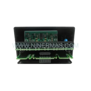
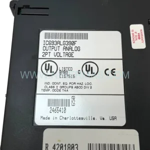
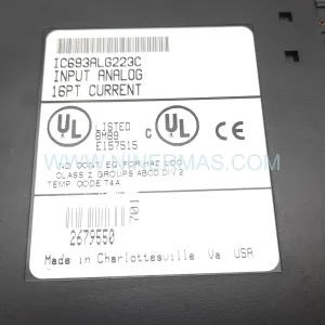
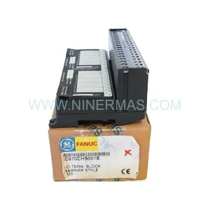
Original Industrial Spare Part
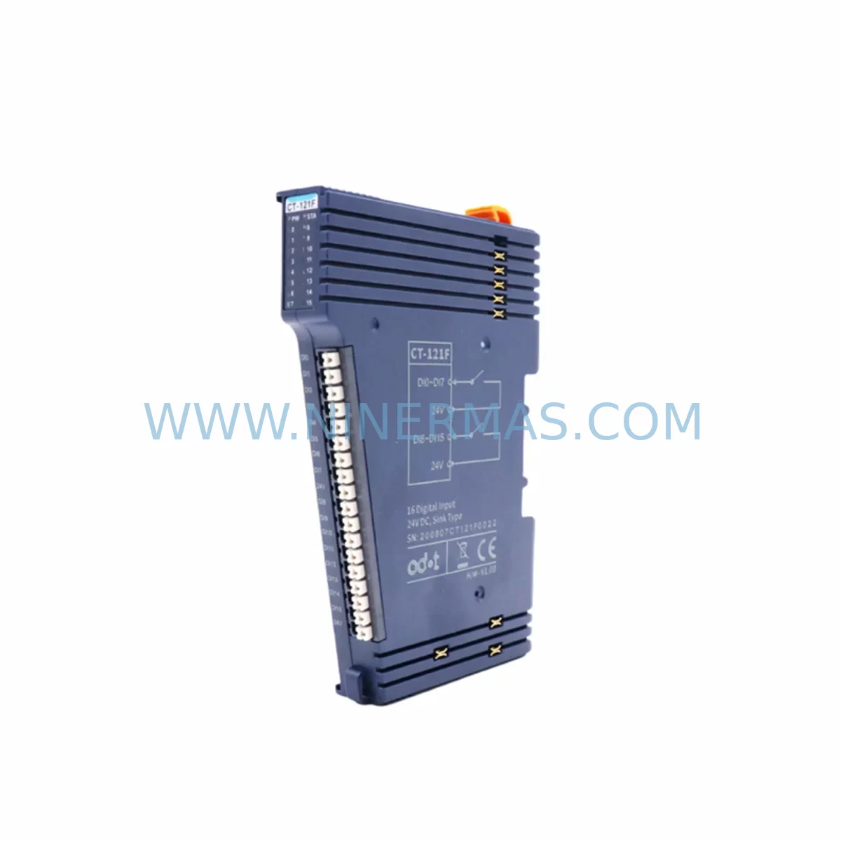
ODOT CT-121F Retrofit-Compatible I/O Expansion Module
Verify the part, confirm the platform family, and move straight into quotation with the right commercial details.
RFQ Ready
- SKUCT-121F
- CategoryPLC & Industrial Automation Modules
- BrandODOT
- SupportAvailability, lead time, condition, and shipping coordination
How Buyers Usually Use This Page
- Confirm the exact part number and platform family before sending the quote request.
- Use direct email when quantity, condition, and destination are already defined internally.
- Switch to the broader brand or category archive when you need alternates nearby.
Series Navigation
Move through the most common platform families behind this part.
Product RFQ
Send this part directly for quotation.
Include quantity, required condition, destination country, and target delivery timing. Current reference: ODOT CT-121F Retrofit-Compatible I/O Expansion Module with SKU CT-121F.
ODOT CT-121F Retrofit-Compatible I/O Expansion Module for Legacy System Upgrades
The ODOT CT-121F is a compact, DIN-rail-mounted I/O expansion module engineered for seamless integration into existing automation architectures. Designed with retrofit engineers and maintenance teams in mind, the CT-121F addresses one of the most persistent challenges in industrial modernization: replacing discontinued or end-of-life I/O modules without triggering a full control system overhaul. Whether you are migrating a legacy production line, upgrading a control cabinet, or extending the service life of an aging PLC platform, the CT-121F delivers the signal compatibility, form factor consistency, and communication reliability that retrofit projects demand.
ODOT’s modular I/O platform is widely adopted across discrete manufacturing, process control, and building automation sectors. The CT-121F slots into the same backplane ecosystem as other ODOT expansion modules, making it a natural fit for engineers already working within the ODOT hardware family. Its terminal block layout follows industry-standard wiring conventions, reducing re-termination time during field installation and minimizing the risk of wiring errors that can extend commissioning windows.
Upgrade Compatibility Table
| Parameter | ODOT CT-121F | Retrofit Notes |
|---|---|---|
| Module Type | I/O Expansion Module | Replaces discontinued analog/digital I/O modules in legacy racks |
| Backplane Interface | ODOT standard backplane bus | Verify backplane slot pitch and connector type before installation |
| Communication Protocol | ODOT internal bus / EtherCAT-compatible platform | Confirm coupler module (e.g., ODOT C-Series coupler) firmware version supports CT-121F |
| Power Supply Requirement | 24 VDC (field-side) | Audit existing PSU capacity; add ODOT PS-series power supply if rail budget is insufficient |
| Terminal Wiring | Removable screw terminal block | Re-use existing field wiring where conductor gauge matches; re-label terminals per new I/O map |
| Module Address | Auto-addressed via coupler scan | Update PLC I/O mapping table and HMI tag database after module insertion |
| Installation Space | DIN rail, standard 35 mm | Measure available rail length in control cabinet; CT-121F width must clear adjacent modules |
| Program Compatibility | Requires I/O re-mapping in PLC project | Back up original PLC program before any hardware swap; validate logic offline if possible |
| HMI Screen Impact | Tag address update required | Update SCADA/HMI tag bindings to reflect new I/O addresses post-swap |
| Warranty | 12-Month Warranty — all units pre-shipment tested under load conditions | |
Retrofit Planning for Existing Automation Systems
A successful CT-121F retrofit begins well before the module arrives on site. The first step is a thorough audit of the existing control cabinet: document every occupied backplane slot, record the current I/O module part numbers, and photograph the terminal wiring before any disconnection. If the legacy system uses an older ODOT coupler or a third-party fieldbus coupler, confirm that the coupler’s firmware is compatible with the CT-121F’s device description file. In EtherCAT-based installations, the ESI (EtherCAT Slave Information) file for the CT-121F must be imported into the engineering tool — typically ODOT’s own configuration software or a compatible IEC 61131-3 programming environment — before the module will be recognized on the network scan.
Power budget verification is a step that retrofit teams frequently underestimate. Each additional I/O expansion module draws current from the backplane power rail. If the existing ODOT PS-series power supply module is already running near capacity — a common situation in cabinets that have been incrementally expanded over years — adding the CT-121F without a power audit can cause intermittent resets or communication faults across the entire I/O station. Calculate the total current draw of all installed modules, including the ODOT C-Series coupler module, any ODOT analog input modules, digital output modules, and safety I/O modules if present, then compare against the rated output of the installed power supply.
Terminal wiring adaptation is the next critical phase. The CT-121F uses a removable screw terminal block, which simplifies field wiring during replacement. However, engineers must verify that the existing field cable conductor gauges fall within the terminal’s rated range. In older installations where field wiring was sized for a different module’s terminal specification, re-termination with appropriately rated conductors may be necessary. Signal isolation requirements should also be reviewed: if the legacy module provided built-in galvanic isolation between field signals and the backplane bus, and the CT-121F’s isolation architecture differs, an external signal isolator module or signal conditioner may need to be inserted in the signal path to maintain electrical separation and protect the controller from field-side transients.
For systems that include an ODOT EtherCAT coupler connecting the I/O station to a host PLC — whether a Beckhoff CX-series controller, a Siemens S7-1500 with EtherCAT master card, or an independent soft PLC — the I/O mapping update must be performed in the PLC project before the new module is powered up in production. Failure to update the process image mapping will result in incorrect data being written to or read from the CT-121F’s channels, potentially causing unintended actuator movement or missed sensor signals. If the host controller uses a programming cable for direct serial or USB connection during commissioning, ensure the cable driver is installed and the project is backed up to a secure location before beginning the swap.
HMI and SCADA systems connected to the control network will also require attention. Any HMI panel — whether a standalone touch panel running a proprietary runtime or a PC-based SCADA station — that displays I/O channel values linked to the replaced module must have its tag database updated to reflect the new I/O addresses. In systems where the HMI communicates directly with the PLC over Ethernet/IP or Modbus TCP, the tag update is straightforward. In older installations using serial communication links, the protocol configuration on both the HMI and the PLC communication port must be verified to remain consistent after the hardware change.
Downtime Control During System Migration
Minimizing production downtime during an I/O module swap requires a structured approach that begins with offline preparation and ends with a disciplined return-to-service sequence. Before the planned maintenance window opens, complete all software-side changes: update the PLC I/O mapping, compile and simulate the modified program offline, update the HMI tag database, and prepare a rollback plan that includes the original program backup and the original module (if it is still functional) staged nearby.
During the physical swap, work methodically through the terminal block. Photograph or sketch the existing wiring before removal. Disconnect field wiring from the old module’s terminal block, remove the module from the backplane slot, insert the CT-121F, and reconnect field wiring to the new terminal block following the updated I/O map. If the terminal block is removable and the wiring pitch is compatible, the entire wired terminal block from the old module may transfer directly — verify this against the CT-121F’s terminal specification before assuming compatibility.
Once the module is seated and wired, power up the I/O station and confirm that the coupler recognizes the CT-121F in its device list. Download the updated PLC program, perform a controlled startup in manual mode, and verify each I/O channel individually before returning the system to automatic operation. This channel-by-channel verification step — checking that each digital input responds to its field device and each digital output drives its actuator correctly — is the single most effective measure for catching wiring errors before they cause a process fault. All ODOT CT-121F units supplied by Ninermas are pre-shipment tested under load conditions, which eliminates module-level defects as a variable during commissioning and allows the site team to focus entirely on integration and configuration.
For systems where even a brief unplanned outage carries significant cost, consider staging the CT-121F installation during a scheduled preventive maintenance window rather than responding reactively to a module failure. Proactive replacement of aging I/O modules — particularly those that have exceeded their manufacturer’s recommended service life or for which spare parts are no longer available — is a core principle of lifecycle-aware maintenance planning. Ninermas maintains stock of the CT-121F and related ODOT I/O expansion modules to support both planned retrofit projects and emergency replacement scenarios, with a 12-month warranty covering all supplied units.
Retrofit Support FAQ
Q1: Is the ODOT CT-121F a direct drop-in replacement for my existing I/O module?
The CT-121F is designed for use within the ODOT modular I/O platform. Whether it is a direct drop-in replacement depends on the specific legacy module being replaced. Key factors to verify include backplane slot compatibility, terminal block wiring pitch, channel count and signal type (digital vs. analog), and the coupler module’s firmware support for the CT-121F device description. Contact our technical team with your existing module part number for a compatibility assessment before ordering.
Q2: What commissioning steps are required after installing the CT-121F?
After physical installation, the required commissioning steps are: (1) confirm the coupler recognizes the CT-121F in its device scan; (2) download the updated PLC program with the revised I/O mapping; (3) update HMI/SCADA tag bindings; (4) verify each I/O channel individually in manual mode; and (5) perform a controlled return to automatic operation. All units are pre-shipment tested, so module-level verification is already complete before delivery.
Q3: Can the CT-121F be used with communication protocols other than ODOT’s native bus?
The CT-121F operates on ODOT’s internal backplane bus and communicates with the host controller through the ODOT coupler module. The coupler determines the fieldbus protocol presented to the host — options within the ODOT platform include EtherCAT, Modbus TCP, PROFINET, and EtherNet/IP depending on the coupler model selected. The CT-121F itself does not require protocol-specific configuration; protocol selection and address assignment are managed at the coupler level.
Q4: What warranty and stock availability does Ninermas provide for the CT-121F?
All ODOT CT-121F units supplied by Ninermas carry a 12-month warranty covering manufacturing defects and functional failures under normal operating conditions. Units are pre-shipment tested before dispatch. Ninermas maintains active stock of the CT-121F to support both planned retrofit projects and urgent replacement requirements. For current lead times and quantity availability, contact sale@ninermas.com or call +0086 187 5021 5667.
| Product Series | Other series |
|---|
Catalog Continuation
More ODOT modules in the catalog.
Use the brand lane to compare nearby part numbers, platform-adjacent modules, and other inquiry-ready listings before sending your final RFQ.
Catalog Continuation
Alternative parts within PLC & Industrial Automation Modules.
Stay inside the same system family when you need substitutes, adjacent modules, or a broader shortlist for procurement review.
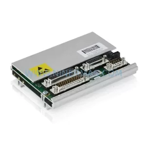
SKU: ZINT-541 3AUA00000658960
ABB ZINT-541 3AUA00000658960 Retrofit-Compatible Inverter Power Module
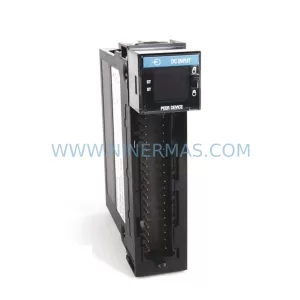
SKU: DSQC633 3HAC022286-001
ABB DSQC633 3HAC022286-001 Service-Ready Spare Part
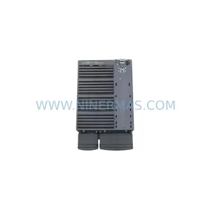
SKU: 6SL3224-0BE33-7UA0
Siemens 6SL3224-0BE33-7UA0 Service-Ready Spare Part