Original Industrial Spare Part
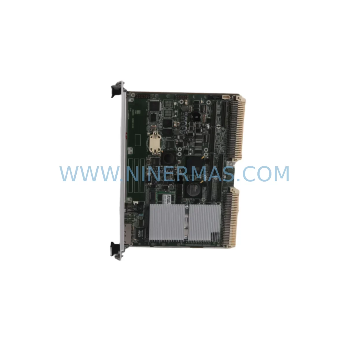
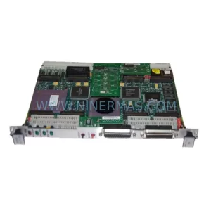
Motorola MVME31006E-1152 Retrofit-Compatible CPU for Legacy Systems
Verify the part, confirm the platform family, and move straight into quotation with the right commercial details.
RFQ Ready
- SKUMVME31006E-1152
- CategoryPLC & Industrial Automation Modules
- BrandMotorola
- SupportAvailability, lead time, condition, and shipping coordination
How Buyers Usually Use This Page
- Confirm the exact part number and platform family before sending the quote request.
- Use direct email when quantity, condition, and destination are already defined internally.
- Switch to the broader brand or category archive when you need alternates nearby.
Series Navigation
Move through the most common platform families behind this part.
Product RFQ
Send this part directly for quotation.
Include quantity, required condition, destination country, and target delivery timing. Current reference: Motorola MVME31006E-1152 Retrofit-Compatible CPU for Legacy Systems with SKU MVME31006E-1152.
Motorola MVME31006E-1152 Retrofit-Compatible CPU for Legacy Systems
The Motorola MVME31006E-1152 is a high-performance VMEbus single-board computer module engineered for demanding industrial control environments. As a retrofit-compatible replacement for legacy MVME Series CPU modules, the MVME31006E-1152 delivers a smooth upgrade path for plant engineers and maintenance teams managing end-of-life control infrastructure. Whether you are restoring a failed system, extending the operational life of an existing VMEbus rack, or executing a planned migration away from discontinued hardware, this module provides the processing power, backplane compatibility, and I/O flexibility required to maintain production continuity with minimal downtime.
The MVME31006E-1152 is built on Motorola’s proven MVME architecture, making it directly relevant to facilities running legacy MVME162, MVME167, MVME172, MVME177, MVME2100, MVME2300, or MVME3100 series controllers. Its VME64x-compliant backplane interface ensures physical and electrical compatibility with standard 6U VMEbus chassis and transition modules, reducing the need for mechanical modifications during installation. The -1152 suffix designates a specific memory and clock configuration that aligns with common factory automation and process control deployments where deterministic cycle times and reliable memory addressing are critical.
Upgrade Compatibility Table
| Parameter | MVME31006E-1152 (Replacement) | Typical Legacy Module | Notes |
|---|---|---|---|
| Form Factor | 6U VMEbus Single-Board Computer | 6U VMEbus SBC | Direct mechanical fit in standard VME chassis |
| Backplane Interface | VME64x / VME32 compatible | VME32 | Backward compatible; verify J1/J2 connector pinout |
| Memory Configuration | -1152 variant (ECC SDRAM) | Varies by legacy SKU | Confirm address map with existing firmware |
| Communication Ports | Dual Ethernet, Serial (RS-232/RS-422) | Single Ethernet or Serial only | Additional port enables Modbus TCP / PROFIBUS gateway |
| OS / Firmware | VxWorks / LynxOS / Linux compatible | VxWorks 5.x typical | BSP update may be required; retain original boot ROM |
| Installation Space | Single VME slot (6U) | Single VME slot (6U) | No chassis modification required |
| Retrofit Recommendation | Direct replacement or slot-for-slot swap | — | Verify IRQ and slot addressing before power-on |
| Commissioning Focus | Boot sequence, memory map, I/O scan rate | — | Use existing ladder logic or function block backup |
| Warranty | 12 Months | EOL — no OEM support | Covered by NINERMAS 12-month warranty policy |
Retrofit Planning for Existing Automation Systems
Successful integration of the MVME31006E-1152 into an existing VMEbus control cabinet begins well before the module arrives on site. Maintenance engineers should start by auditing the current rack configuration, documenting every occupied slot, the installed MVME162 or MVME167 CPU card, any MVME712 transition modules, MVME374 memory expansion boards, and the MVME230 or MVME712M serial I/O boards that handle field device communication. This inventory forms the baseline for your compatibility verification checklist.
Power budget is a critical first step. The MVME31006E-1152 draws its supply from the VMEbus backplane’s +5 V and ±12 V rails. Before installation, measure the existing power supply output — typically an MVME-compatible 19-inch rack PSU — and confirm that the available headroom exceeds the module’s rated current draw by at least 20%. If the existing power supply is already near capacity due to additional MVME374 memory boards or MVME218 SCSI controllers sharing the same backplane, a power supply upgrade or load redistribution across a secondary chassis may be necessary.
Terminal wiring and I/O mapping deserve equal attention. Field devices connected through MVME712 transition modules or third-party I/O breakout panels must be re-verified against the new module’s connector pinout. RS-232 and RS-422 serial links to legacy HMI panels — including older Motorola-branded operator terminals or third-party SCADA workstations running proprietary communication drivers — must be tested for baud rate, parity, and stop-bit compatibility before the system is returned to automatic mode. Where the original system used a dedicated MVME-ISIO or MVME-IPIC IndustryPack carrier for specialized analog I/O, confirm that the IP module addressing scheme is preserved in the new BSP configuration.
For facilities migrating from serial Modbus RTU to Ethernet-based Modbus TCP, the MVME31006E-1152’s dual Ethernet ports provide a direct upgrade path without requiring an external protocol converter. This is particularly valuable in water treatment, oil and gas, and discrete manufacturing environments where the control network is being modernized in parallel with the hardware refresh. The secondary Ethernet port can be dedicated to a maintenance VLAN, enabling remote diagnostics without exposing the primary control network.
Backplane slot addressing must be confirmed before power-on. VMEbus systems use geographic addressing (GA lines) to assign slot numbers, and the MVME31006E-1152 must be installed in the same physical slot as the module it replaces — or the system monitor firmware must be updated to reflect the new slot assignment. Failure to align slot addressing with the existing software configuration is one of the most common causes of post-replacement boot failures in MVME-based systems.
Where the original control system included an MVME-IPMC761 or similar IPMI-capable management controller, verify that the new module’s IPMI interface is correctly configured for the existing chassis management network. This is especially relevant in redundant control architectures where a secondary MVME3100 or MVME2300 module provides hot-standby capability and relies on accurate slot and chassis identity information to execute a clean failover.
Downtime Control During System Migration
Minimizing unplanned downtime during a VMEbus CPU replacement requires a structured pre-migration protocol. Begin by creating a full backup of the existing application program — whether stored in flash memory on the original MVME167 or MVME172 module, on a connected MVME-SCSI disk, or in a networked file system accessible via the onboard Ethernet port. This backup must include not only the compiled application binary but also the BSP configuration file, the boot script, and any environment variables stored in NVRAM. Losing NVRAM content during a module swap is a common source of extended downtime, as re-entering network addresses, boot device paths, and startup parameters manually can consume hours of engineering time.
Where production schedules permit, perform a bench test of the MVME31006E-1152 before the scheduled maintenance window. Load the backed-up application onto the replacement module in a test rack, verify the boot sequence, confirm that all I/O scan tasks initialize correctly, and validate communication with a representative sample of field devices using a portable Modbus or serial test tool. This pre-commissioning step typically reduces on-site installation time from several hours to under 60 minutes.
During the actual swap, follow a strict sequence: isolate the control cabinet from field power, document the physical wiring to the MVME712 transition module or I/O breakout panel, remove the failed or end-of-life CPU module, install the MVME31006E-1152 in the same slot, reconnect all transition module cables, restore power, and monitor the boot sequence on the serial console port before re-enabling field I/O. This disciplined approach protects the original program logic, preserves HMI screen tag mappings, and maintains communication link integrity across the migration event.
For critical processes where even a planned maintenance window carries significant production risk, consider a parallel-run strategy: install the MVME31006E-1152 in an adjacent slot in a secondary chassis, mirror the I/O configuration, and perform a controlled switchover during a low-demand period. This approach is particularly effective in continuous process industries where a cold restart of the control system carries additional risks beyond the module replacement itself.
Retrofit Support FAQ
Q1: Is the MVME31006E-1152 a direct drop-in replacement for the MVME3100 series?
The MVME31006E-1152 is mechanically and electrically compatible with standard 6U VMEbus chassis used across the MVME3100 family. However, firmware and BSP differences between specific -suffix variants mean that a direct application binary transfer may require recompilation or BSP parameter adjustment. We recommend confirming the boot ROM version and memory map configuration before final installation. Our technical team can assist with pre-shipment configuration verification upon request.
Q2: What commissioning steps are required after installation?
After physical installation, the primary commissioning steps are: (1) verify slot addressing via the GA lines, (2) confirm NVRAM parameters including boot device, IP address, and startup script path, (3) load the application binary and execute a dry-run with field I/O isolated, (4) verify serial and Ethernet communication links to HMI and SCADA systems, and (5) re-enable field I/O and monitor the first full scan cycle for any address or timing anomalies. A commissioning checklist is available upon request.
Q3: How is the module tested before shipment?
Every MVME31006E-1152 unit undergoes a full power-on self-test (POST) and functional verification prior to shipment. Testing covers memory integrity, Ethernet port link negotiation, serial port loopback, and VMEbus arbitration response. Units that do not pass all test criteria are not shipped. A test report is available upon request for quality-critical applications.
Q4: What does the 12-month warranty cover, and what is the inventory availability?
The MVME31006E-1152 is covered by NINERMAS’s 12-month warranty against manufacturing defects and functional failures under normal operating conditions. Warranty service includes repair or replacement at no additional cost. We maintain dedicated stock of MVME Series modules to support urgent replacement requirements, with standard lead times of 3–7 business days for in-stock units and expedited shipping available for critical downtime situations. Contact our team for real-time inventory confirmation before placing a time-sensitive order.
| Product Series | Legacy |
|---|
Catalog Continuation
More Motorola modules in the catalog.
Use the brand lane to compare nearby part numbers, platform-adjacent modules, and other inquiry-ready listings before sending your final RFQ.
Catalog Continuation
Alternative parts within PLC & Industrial Automation Modules.
Stay inside the same system family when you need substitutes, adjacent modules, or a broader shortlist for procurement review.
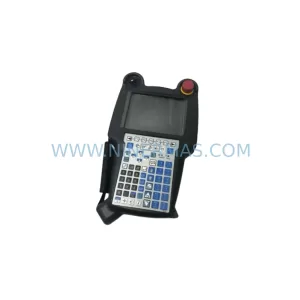
SKU: A05B-2518-C200
FANUC A05B-2518-C200 Retrofit Teach Pendant for Legacy Systems
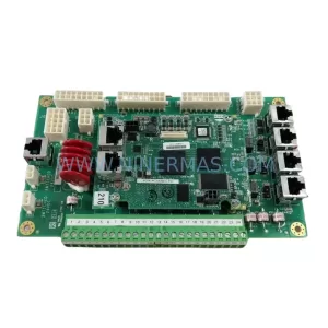
SKU: 2711PC-T10C4D8
Allen-Bradley 2711PC-T10C4D8 Retrofit-Compatible HMI Terminal