Original Industrial Spare Part
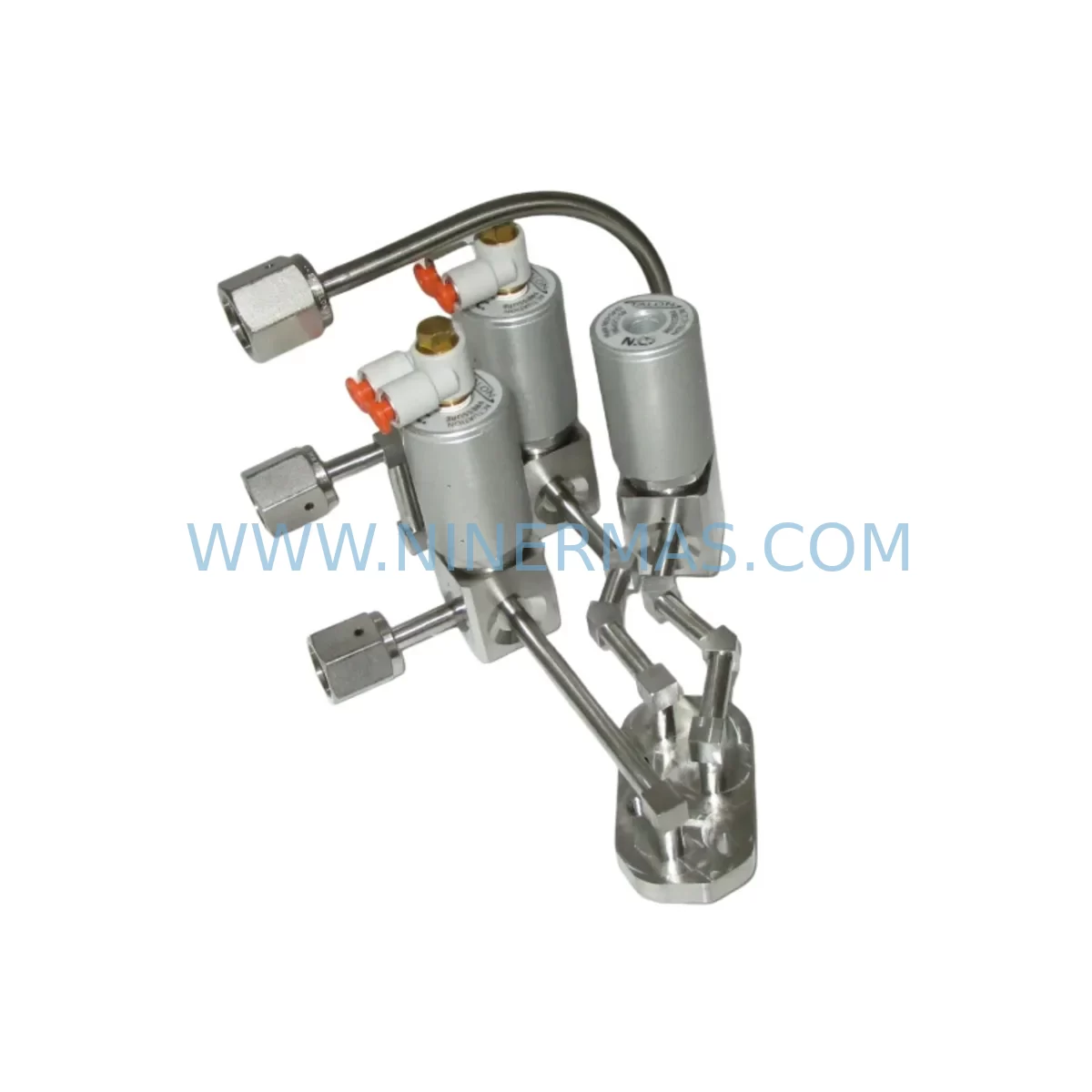
LAM 839-182861-001 Retrofit Valve Module for Legacy Systems
Verify the part, confirm the platform family, and move straight into quotation with the right commercial details.
RFQ Ready
- SKU839-182861-001 0100-00698 0090-02346 0010-09348
- CategoryPLC & Industrial Automation Modules
- BrandLam Research
- SupportAvailability, lead time, condition, and shipping coordination
How Buyers Usually Use This Page
- Confirm the exact part number and platform family before sending the quote request.
- Use direct email when quantity, condition, and destination are already defined internally.
- Switch to the broader brand or category archive when you need alternates nearby.
Series Navigation
Move through the most common platform families behind this part.
Product RFQ
Send this part directly for quotation.
Include quantity, required condition, destination country, and target delivery timing. Current reference: LAM 839-182861-001 Retrofit Valve Module for Legacy Systems with SKU 839-182861-001 0100-00698 0090-02346 0010-09348.
LAM 839-182861-001 Retrofit Valve Module for Legacy Systems: Seamless Compatibility and Smooth Upgrade
The LAM 839-182861-001 is a retrofit-compatible pneumatic diaphragm valve module engineered for direct integration into legacy semiconductor fabrication equipment. As Lam Research’s installed base of older etch, deposition, and clean systems continues to operate well beyond original design lifespans, the demand for reliable, drop-in replacement valve assemblies has grown significantly. This module addresses that need by maintaining full mechanical and functional compatibility with the original diaphragm valve series, enabling facilities to extend equipment service life without committing to full platform replacement.
Designed for use in process gas delivery, vacuum isolation, and chemical distribution circuits, the 839-182861-001 supports the precise flow control requirements of legacy chamber architectures. Its pneumatic actuation mechanism is compatible with standard shop-air supply systems operating at 60–80 PSI, and the valve body dimensions conform to the original mounting footprint, eliminating the need for bracket modifications or manifold rework during installation.
Before initiating a replacement, engineers should verify the following parameters against the existing system documentation: supply pressure rating, port thread specification (typically 1/4-inch NPT or VCR), actuator stroke length, and the valve’s normally-open or normally-closed configuration. Mismatches in any of these areas can result in process gas leakage, chamber pressure instability, or unintended valve state during power loss events — all of which carry significant safety implications in semiconductor fab environments.
Upgrade Compatibility Table
| Parameter | Original Specification | 839-182861-001 Retrofit Spec | Notes |
|---|---|---|---|
| Valve Type | Pneumatic Diaphragm | Pneumatic Diaphragm | Direct form-factor match |
| Actuation Pressure | 60–80 PSI | 60–80 PSI | Standard shop-air compatible |
| Port Configuration | 1/4″ NPT / VCR | 1/4″ NPT / VCR | Confirm thread type before installation |
| Mounting Footprint | Original LAM bracket | Identical to OEM | No bracket modification required |
| Normally Closed / Open | NC (default) | NC (default) | Verify against P&ID drawing |
| Communication Interface | Discrete I/O signal | Discrete I/O signal | Compatible with existing I/O modules |
| Installation Space | Standard gas box bay | Identical envelope | No enclosure modification needed |
| Commissioning Requirement | Leak check + functional test | Leak check + functional test | Helium leak test recommended |
| Warranty | N/A (legacy) | 12-Month Warranty | Covers defects under normal operating conditions |
Retrofit Planning for Existing Automation Systems
Successful integration of the LAM 839-182861-001 into an existing process system requires a structured retrofit plan that accounts for both mechanical and control-layer dependencies. In most legacy Lam Research platforms — including older Versys, Exelan, and 2300 series chambers — the diaphragm valve assembly is part of a larger gas delivery manifold that may include multiple valve stations, mass flow controllers, and pressure transducers operating in sequence.
During retrofit planning, technicians should map the valve’s position within the gas stick and identify all upstream and downstream components that share the same pneumatic supply rail. In many installations, the 839-182861-001 operates alongside related valve assemblies such as the LAM 839-182860-001 and 839-182862-001, which serve adjacent gas lines within the same manifold block. Replacing only the failed valve without inspecting neighboring units can result in recurring failures if the root cause is a contaminated pneumatic supply or degraded solenoid driver output.
The solenoid valve driver board — often a dedicated I/O module such as the LAM 839-009958-001 or a compatible discrete output card — must be verified for proper voltage output (typically 24 VDC) before the new valve is energized. A weak or intermittent driver signal is a common cause of premature diaphragm fatigue and should be ruled out during the pre-installation checklist.
For systems using a centralized valve manifold assembly, the LAM 839-013282-001 manifold block and associated pneumatic fittings should be inspected for internal contamination or cracking. If the manifold shows signs of chemical attack from process gases such as HCl, Cl₂, or NF₃, replacement of the manifold body alongside the valve module is strongly recommended to prevent recontamination of the new diaphragm.
On the control side, the replacement valve must be mapped to the correct I/O address in the chamber controller. In older Lam platforms, this mapping is defined in the equipment software configuration file and must match the physical wiring termination at the I/O backplane. Technicians should cross-reference the wiring diagram with the terminal block labeling to confirm that the valve’s open and closed feedback signals — if present — are correctly assigned. Failure to verify this mapping can result in the HMI displaying an incorrect valve state, which may trigger false interlock conditions or mask actual process faults.
Where the system uses a programmable logic controller for valve sequencing, the PLC ladder logic should be reviewed to confirm that the new valve’s response time falls within the expected timing window. The 839-182861-001’s actuation speed is consistent with the original specification, but any changes to pneumatic tubing length or fitting configuration during installation can affect response time and should be compensated for in the timing parameters if necessary.
Additional components commonly involved in the same retrofit scope include the LAM 839-182863-002 pressure regulator assembly, the 839-009959-003 solenoid coil assembly, and the 839-013283-002 pneumatic tubing manifold. These components share the same service interval and are frequently replaced as a group to minimize future unplanned downtime.
Downtime Control During System Migration
Minimizing unplanned downtime during a valve replacement is a primary concern for fab operations teams, where each hour of chamber downtime translates directly to lost wafer throughput. The LAM 839-182861-001’s drop-in compatibility is the single most important factor in reducing mean time to repair (MTTR), as it eliminates the need for mechanical adaptation, software reconfiguration, or process requalification in most standard replacement scenarios.
To further reduce downtime, facilities should maintain a pre-staged replacement kit that includes the valve module, a set of VCR gaskets, pneumatic fittings, and a spare solenoid coil. Having these components available at the point of use — rather than sourced from a central warehouse during an active breakdown — can reduce repair time from several hours to under 60 minutes in straightforward cases.
Before removing the failed valve, the gas line must be purged and the chamber brought to a safe atmospheric condition. The pneumatic supply to the affected valve station should be isolated at the nearest upstream shutoff, and the solenoid driver output should be de-energized and locked out. Following installation of the 839-182861-001, a helium leak check at all VCR connections is mandatory before gas flow is restored. The leak check should be performed at the system’s maximum operating pressure and documented in the maintenance log.
Original program logic does not require modification in standard replacement scenarios, as the new valve maintains the same electrical interface and response characteristics as the original. However, if the replacement is part of a broader control system upgrade — for example, migrating from a legacy Lam controller to a third-party PLC or DCS platform — the valve’s I/O mapping, interlock logic, and HMI faceplate assignments must all be validated against the new control architecture before the chamber is returned to production.
Retrofit Support FAQ
Q1: Is the LAM 839-182861-001 a direct replacement for the original diaphragm valve in my legacy Lam Research system?
A: Yes. The 839-182861-001 is designed as a form-fit-function replacement for the original diaphragm valve assembly used in the specified Lam Research diaphragm valve series. The mounting dimensions, port configuration, and actuation pressure are identical to the original specification. No mechanical modification is required for standard installations. Confirm the normally-closed or normally-open configuration against your system’s P&ID drawing before installation.
Q2: What commissioning steps are required after installing the 839-182861-001?
A: After mechanical installation, perform a helium leak check at all VCR connections at the system’s maximum operating pressure. Verify the solenoid driver output voltage (typically 24 VDC) and confirm the valve’s open/closed feedback signals are correctly mapped in the I/O configuration. Cycle the valve a minimum of five times under controlled conditions before restoring process gas flow. Document all commissioning results in the equipment maintenance log.
Q3: Does NINERMAS pre-test the 839-182861-001 before shipment?
A: Yes. All units undergo functional testing prior to shipment, including actuation cycle verification and leak integrity checks. Each unit is shipped with a test report confirming it meets the original performance specification. The 839-182861-001 is covered by a 12-month warranty against manufacturing defects under normal operating conditions.
Q4: What is the typical lead time and inventory availability for the 839-182861-001?
A: NINERMAS maintains reserved inventory of the 839-182861-001 to support urgent replacement requirements. Standard orders are processed and shipped within 3–5 business days. For facilities with recurring demand, long-term supply agreements and reserved stock programs are available to eliminate lead time uncertainty and support planned maintenance schedules. Contact our team at sale@ninermas.com or +0086 187 5021 5667 for availability confirmation.
| Product Series | Legacy |
|---|
Catalog Continuation
More Lam Research modules in the catalog.
Use the brand lane to compare nearby part numbers, platform-adjacent modules, and other inquiry-ready listings before sending your final RFQ.
SKU: 710-073479-215 810-073479-215 5V - 15V X9-2L2L1D-000001 5V - 12V X7-2D2J2J-000001
LAM RESEARCH 710-073479-215 Retrofit PCB for Legacy Systems
SKU: DGF 710-031325-002 810-031325-002 LAM 716-443129-001 10320294 810-UNV
Lam 710-031325-002 Retrofit-Compatible DGF for Legacy Systems
SKU: 810-802799-010 810-031325-003 0021-28413 0021-32929
Lam Research 810-802799-010 Retrofit Module for Legacy Systems
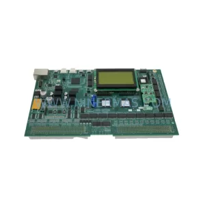
SKU: UI/FIB JTS SIH4 W/ BD 24 810-111093-100 C1848 , TVB41D-1/TMP 1D81-000140 853-250063-007
Lam Research 810-111093-100 Retrofit Gas Module for Legacy Systems
Catalog Continuation
Alternative parts within PLC & Industrial Automation Modules.
Stay inside the same system family when you need substitutes, adjacent modules, or a broader shortlist for procurement review.
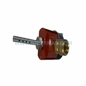
SKU: TRY/PRG/4-20MA/10-30DC
MOORE TRY/PRG/4-20MA/10-30DC Service-Ready Spare Part
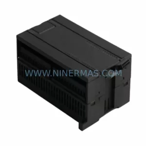
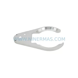
SKU: 5085-404901-11 12INCH 2910-202413-12 404200XRMPD2H14 7-249717
TEL 5085-404901-11 Service-Ready Spare Part for Industrial Maintenance
SKU: DIP011 05-058-011
SIGMATEK DIP011 05-058-011 Service-Ready Spare Part