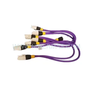
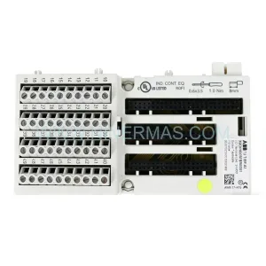
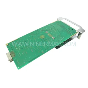
Original Industrial Spare Part
KSL 2401-30056 Retrofit-Compatible Fiber Optic Module
Verify the part, confirm the platform family, and move straight into quotation with the right commercial details.
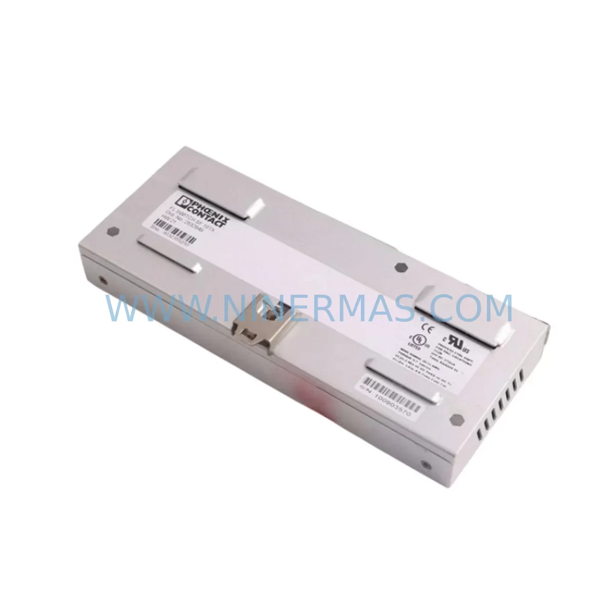
RFQ Ready
- SKU2401-30056
- CategoryPLC & Industrial Automation Modules
- BrandKSL
- SupportAvailability, lead time, condition, and shipping coordination
How Buyers Usually Use This Page
- Confirm the exact part number and platform family before sending the quote request.
- Use direct email when quantity, condition, and destination are already defined internally.
- Switch to the broader brand or category archive when you need alternates nearby.
Series Navigation
Move through the most common platform families behind this part.
Product RFQ
Send this part directly for quotation.
Include quantity, required condition, destination country, and target delivery timing. Current reference: KSL 2401-30056 Retrofit-Compatible Fiber Optic Module with SKU 2401-30056.
KSL 2401-30056 Retrofit-Compatible Fiber Optic Module: Legacy System Compatibility and Smooth Upgrade Path
The KSL 2401-30056 is a retrofit-compatible fiber optic module engineered for seamless integration into aging industrial control architectures. As automation systems built on legacy communication backbones approach end-of-life, the 2401-30056 provides a reliable, field-proven replacement path that preserves existing wiring infrastructure, minimizes engineering rework, and reduces unplanned downtime. Whether you are upgrading a distributed control system (DCS), modernizing a programmable logic controller (PLC) rack, or restoring a failed fiber link in a process plant, the KSL 2401-30056 delivers the optical performance and mechanical compatibility required for mission-critical retrofit projects.
Fiber optic communication modules such as the 2401-30056 are central to high-noise industrial environments where copper-based signal transmission is susceptible to electromagnetic interference. In steel mills, chemical processing plants, power generation facilities, and automotive assembly lines, fiber optic links provide the galvanic isolation and bandwidth necessary to maintain deterministic control loop performance. The KSL 2401-30056 supports these demanding applications with a compact form factor designed to fit standard backplane slots found in legacy control cabinets.
When planning a retrofit around the 2401-30056, engineers must verify several critical compatibility parameters before committing to installation. The optical wavelength and connector type — typically ST or SMA — must match the existing fiber plant. Cable attenuation budgets should be recalculated if the original module specifications are unavailable, particularly on long runs exceeding 500 meters. Backplane slot pitch and edge connector pinout must be confirmed against the target rack, whether that is a KSL-series chassis or a third-party carrier compatible with the module’s form factor. Power supply rail requirements — commonly +5 VDC and ±15 VDC — should be validated against the existing KSL power supply module installed in the rack, such as a KSL 2401-10012 or equivalent regulated DC supply unit.
Terminal wiring on the field side requires careful attention during changeover. If the legacy module used screw-terminal I/O blocks, the replacement 2401-30056 must be confirmed to use the same terminal pitch and signal polarity. In systems where the fiber optic module interfaces with analog input modules or digital output modules on the same backplane, the inter-module communication protocol — whether proprietary KSL bus or a standard such as PROFIBUS or Modbus RTU — must remain uninterrupted during the swap. Technicians should document the existing module address settings, DIP switch configurations, and any jumper positions before removal to ensure the replacement module is configured identically.
Program logic compatibility is another key consideration. In PLC-based systems, the I/O map assigned to the fiber optic module’s communication channel must be preserved in the controller program. If the host controller is a legacy unit such as a KSL 2401-CPU or a compatible third-party processor, the rack configuration file in the programming software must reflect the new module without requiring a full program recompile. Where HMI screens reference specific channel tags tied to the fiber optic link, those tag bindings should be verified post-installation to confirm that operator displays continue to reflect live process values without alarm flooding or communication fault indications.
Communication link integrity testing is mandatory before returning the system to automatic control. A fiber optic power meter and light source should be used to verify end-to-end optical loss on each fiber strand connected to the 2401-30056. Acceptable loss margins vary by system design, but a general guideline of less than 3 dB total path loss is appropriate for most industrial fiber optic control links. If the system uses a KSL fiber optic repeater module or optical splitter in the signal path, those components should also be inspected for degradation during the retrofit window.
Installation space confirmation is essential in densely populated control cabinets. The 2401-30056 occupies a defined slot width in the KSL backplane, and adjacent modules — including I/O expansion modules, communication interface cards, and signal isolator units — must not obstruct the fiber connector access points on the front face of the module. Cable management for the fiber pigtails requires bend radius protection to prevent signal loss from micro-bending, particularly in cabinets where fiber runs must navigate around power distribution blocks or terminal strips.
All KSL 2401-30056 units supplied by NINERMAS undergo pre-shipment functional testing to verify optical transmitter power output, receiver sensitivity, and backplane communication handshake. Each module is shipped with a test report confirming performance within KSL factory specifications. A 12-month warranty covers defects in materials and workmanship from the date of delivery, supporting lifecycle extension programs for plants that must maintain aging control systems beyond the original equipment manufacturer’s support window.
Upgrade Compatibility Table
| Parameter | KSL 2401-30056 Specification | Retrofit Consideration |
|---|---|---|
| Module Type | Fiber Optic Communication Module | Confirm slot type matches target KSL backplane |
| Optical Connector | ST / SMA (verify per unit label) | Match to existing fiber plant connector type |
| Communication Protocol | KSL proprietary / PROFIBUS-compatible | Verify host controller protocol configuration |
| Power Supply Requirement | +5 VDC, ±15 VDC (backplane-supplied) | Confirm rack power supply capacity before insertion |
| Installation Format | Single-slot backplane card | Verify slot pitch and adjacent module clearance |
| Address Configuration | DIP switch / jumper selectable | Document legacy settings before module removal |
| HMI Compatibility | Tag-based via host controller | Verify tag bindings post-installation |
| Pre-Shipment Testing | Full functional test included | Test report provided with each unit |
| Warranty | 12 Months from delivery | Covers materials and workmanship defects |
| Replacement Compatibility | Drop-in for legacy KSL 2401-series fiber modules | Confirm firmware version compatibility with host CPU |
Retrofit Planning for Existing Automation Systems
A successful retrofit centered on the KSL 2401-30056 typically begins with a full audit of the existing control cabinet. Engineers should map every module installed in the KSL backplane or compatible rack, including the CPU module, power supply unit, analog input cards, digital output modules, and any communication gateway cards bridging legacy protocols to modern Ethernet-based networks. In systems where a KSL fiber optic repeater extends the communication link to a remote I/O station, the repeater’s optical budget must be recalculated after the 2401-30056 is installed to confirm that the end-to-end link margin remains within specification.
Where the control system includes a KSL programming cable or dedicated configuration interface, the module’s internal parameters should be read and saved before the old unit is removed. This backup ensures that if the replacement module requires parameter initialization, the original configuration can be restored without relying on incomplete documentation. In plants running continuous processes — such as chemical reactors, paper machines, or water treatment systems — the retrofit window must be coordinated with production scheduling to minimize exposure to uncontrolled process states during the module changeover.
Signal isolator modules installed between the fiber optic module and field transmitters should be inspected during the retrofit. Aging signal isolators can introduce offset errors or increased noise that may be incorrectly attributed to the new fiber module after installation. Similarly, any optical patch panels or fiber distribution frames in the signal path should be cleaned and inspected for contamination on the ferrule faces, as dirty connectors are a leading cause of intermittent fiber link faults in industrial environments.
For systems migrating from legacy serial communication to modern fieldbus or industrial Ethernet, the 2401-30056 may serve as an interim solution that maintains the existing fiber infrastructure while a phased migration to PROFINET, EtherNet/IP, or Modbus TCP is planned. In this scenario, a protocol converter or communication gateway module can be installed in parallel with the KSL fiber module to bridge the legacy control network to the new supervisory layer without requiring a full system cutover.
Downtime Control During System Migration
Minimizing downtime during a fiber optic module replacement requires disciplined pre-work and a clearly defined cutover sequence. Before the maintenance window opens, the replacement KSL 2401-30056 should be bench-tested against a known-good backplane to confirm that the module powers up correctly and passes the internal self-test routine. The host controller program should be backed up to an offline storage device, and the current I/O force table should be documented so that any forced outputs can be reinstated immediately if the controller enters a fault state during the module swap.
During the cutover, the fiber optic cables should be labeled and photographed before disconnection to prevent incorrect reconnection after the new module is seated. The module should be inserted into the backplane with the rack power de-energized to prevent hot-insertion damage to the backplane bus. After power is restored, the host controller’s diagnostic display or programming software should be used to confirm that the 2401-30056 is recognized on the rack and that no communication fault codes are active.
If the system uses a redundant fiber optic link — common in safety-instrumented systems and high-availability process control applications — the redundant path should remain active throughout the primary module replacement to maintain control continuity. Once the primary 2401-30056 is confirmed operational, the redundant path can be tested independently without interrupting the live control loop. This approach limits the exposure window to the time required for physical module replacement and initial communication verification, typically 15 to 30 minutes for an experienced technician working from a prepared procedure.
Post-installation, a full I/O checkout should be performed to confirm that all field signals are reading correctly through the new fiber module. Any discrepancies in analog signal scaling or digital input state should be investigated before the system is returned to automatic control. The completed retrofit should be documented in the plant’s maintenance management system, including the module serial number, installation date, optical loss measurements, and the technician’s sign-off, to support future maintenance planning and warranty claim processing.
Retrofit Support FAQ
Q: Is the KSL 2401-30056 a direct drop-in replacement for other KSL 2401-series fiber optic modules?
A: The 2401-30056 is designed as a retrofit-compatible replacement within the KSL 2401 series. Before installation, confirm that the slot pinout, optical connector type, and communication protocol configuration match the module being replaced. In most cases, DIP switch settings from the original module can be replicated on the 2401-30056 to restore the original channel address and protocol parameters without modifying the host controller program.
Q: What pre-shipment testing is performed on each 2401-30056 unit?
A: Every KSL 2401-30056 supplied by NINERMAS undergoes a full functional test covering optical transmitter output power, receiver sensitivity threshold, backplane communication handshake, and power supply rail verification. A written test report is included with each shipment. Units that do not meet KSL factory specifications are not shipped.
Q: What is the warranty coverage for the KSL 2401-30056?
A: NINERMAS provides a 12-month warranty from the date of delivery covering defects in materials and workmanship. The warranty supports return-and-replace processing for confirmed defective units. Warranty claims should be initiated by contacting sale@ninermas.com with the unit serial number and a description of the observed fault.
Q: How quickly can the KSL 2401-30056 be delivered for an urgent retrofit project?
A: NINERMAS maintains stock of the KSL 2401-30056 to support urgent spare parts requirements. Standard lead times and expedited shipping options are available. Contact sale@ninermas.com or call +0086 187 5021 5667 to confirm current stock availability and arrange priority dispatch for time-critical maintenance windows.
| Product Series | Other series |
|---|
Catalog Continuation
Alternative parts within PLC & Industrial Automation Modules.
Stay inside the same system family when you need substitutes, adjacent modules, or a broader shortlist for procurement review.
SKU: E19299450 E19299451 W/ MERCURY II 6000 ME-88-Y233-1 PCA-28430
Varian E19299450/E19299451 Service-Ready Spare Part
SKU: M-SPS1000RM-1F-0010-10061-0100-20003
Fuji M-SPS1000RM Retrofit Power Supply for Legacy Systems
SKU: 6FC5357-0BB11-0AE1
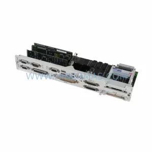
Siemens 6FC5357-0BB11-0AE1 Retrofit NCU for Legacy Systems