Original Industrial Spare Part
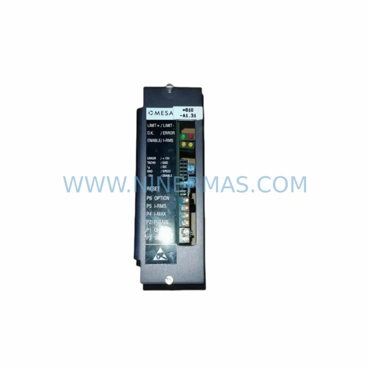
INFRANOR 2404 K81 Retrofit-Compatible Drive Module
Verify the part, confirm the platform family, and move straight into quotation with the right commercial details.
RFQ Ready
- SKU2404 K81
- CategoryPLC & Industrial Automation Modules
- BrandINFRANOR
- SupportAvailability, lead time, condition, and shipping coordination
How Buyers Usually Use This Page
- Confirm the exact part number and platform family before sending the quote request.
- Use direct email when quantity, condition, and destination are already defined internally.
- Switch to the broader brand or category archive when you need alternates nearby.
Series Navigation
Move through the most common platform families behind this part.
Product RFQ
Send this part directly for quotation.
Include quantity, required condition, destination country, and target delivery timing. Current reference: INFRANOR 2404 K81 Retrofit-Compatible Drive Module with SKU 2404 K81.
INFRANOR 2404 K81 Retrofit-Compatible Drive Module for Legacy Automation Systems
The INFRANOR 2404 K81 is a compact, high-performance AC servo drive module designed for seamless integration into existing 2404 Series control architectures. As legacy automation lines face increasing pressure from discontinued OEM support and aging drive infrastructure, the 2404 K81 has become a critical retrofit component for engineers tasked with extending the operational life of servo-controlled machinery without undertaking a full system overhaul. NINERMAS maintains verified in-stock inventory of the 2404 K81 with a 12-month warranty on every unit shipped, supporting procurement teams that require reliable lead times and documented quality assurance.
The 2404 K81 is engineered to interface directly with INFRANOR’s established 2404 Series drive platform, making it a preferred choice for maintenance engineers replacing failed or end-of-life drive modules in multi-axis servo systems. Its compatibility with the existing backplane connector layout, terminal wiring scheme, and module addressing protocol means that in most retrofit scenarios, the replacement can be completed without modifying the host PLC program or reconfiguring the HMI display pages. This dramatically reduces planned downtime and eliminates the risk of introducing software regressions during a critical production window.
Upgrade Compatibility Table
| Parameter | INFRANOR 2404 K81 | Retrofit Notes |
|---|---|---|
| Drive Series | INFRANOR 2404 | Direct series match; no adapter required |
| Backplane Interface | 2404 Series standard connector | Verify slot position and module address before installation |
| Terminal Wiring | Standard screw-terminal block | Confirm wire gauge and torque spec per original drawing |
| Communication Protocol | Analog / Pulse-Direction / CANopen (model-dependent) | Match protocol to host controller output type |
| Power Supply Compatibility | 24 VDC control / AC mains input | Verify bus voltage capacity before energizing |
| Installation Space | Standard 2404 module footprint | Confirm rack slot clearance and ventilation spacing |
| PLC Program Compatibility | Retains original axis address | No program modification required in most cases |
| HMI Screen Impact | Transparent to SCADA/HMI layer | Verify drive status tags post-commissioning |
| Commissioning Requirement | Parameter upload from backup or manual entry | Retain original parameter file before removal |
| Warranty | 12-Month Warranty — All units tested before shipment | |
Retrofit Planning for Existing Automation Systems
Successful integration of the INFRANOR 2404 K81 into a running production environment requires a structured pre-installation audit. Engineers should begin by documenting the existing drive’s parameter set using the INFRANOR programming cable or the drive’s front-panel interface, saving the configuration to a backup file before the old module is removed. This parameter file will be used to restore axis tuning, speed limits, torque thresholds, and fault response settings on the replacement unit.
Power supply capacity is the first hardware constraint to verify. The 2404 K81 draws from the shared DC bus or dedicated AC input depending on the cabinet configuration. If the control cabinet houses multiple INFRANOR 2404 Series drive modules — for example, a multi-axis gantry or coordinated conveyor system — the total bus load must be recalculated to confirm that the existing power supply module can sustain the combined inrush and continuous current demand after the swap. In cabinets where the power supply is already operating near its rated output, a parallel or upgraded supply module may be required before the retrofit proceeds.
Terminal wiring should be mapped against the original electrical schematic. The 2404 K81 uses a screw-terminal interface consistent with the 2404 Series standard, but wire labeling, shield grounding points, and feedback cable routing must be confirmed against the as-built drawing. Encoder feedback cables — typically connected to the motor’s resolver or incremental encoder — must be re-terminated with correct shielding to prevent noise-induced faults after commissioning. If the system uses a separate signal isolator between the controller and the drive’s analog input, the isolator’s output range should be verified against the 2404 K81’s command input specification.
For systems where the host controller communicates via CANopen or a fieldbus protocol, the module node address and baud rate must be set to match the original drive before the network is re-energized. In multi-drop fieldbus topologies, an incorrect node address will cause address conflicts that prevent the entire network segment from initializing. Engineers working on CANopen-based systems should also verify that the termination resistor at the end of the bus segment remains correctly placed after the module swap.
Where the control system includes an HMI or SCADA layer — such as a panel-mounted operator terminal connected via serial or Ethernet — the drive status tags and alarm codes should be verified post-commissioning. In most 2404 Series installations, the HMI communicates with the PLC rather than directly with the drive, so the HMI display pages typically require no modification. However, if the original system used drive-native communication for status readback, the tag mapping should be confirmed against the new module’s register layout.
Rack and backplane installations require confirmation of slot assignment and module addressing. In multi-slot 2404 Series racks, each drive module occupies a defined slot that corresponds to a hardware address used by the host controller for axis identification. The 2404 K81 must be installed in the same slot as the original module, or the axis address must be reconfigured in both the drive and the PLC program. For systems using a dedicated rack backplane with integrated I/O expansion modules, the backplane’s power distribution rails should be inspected for corrosion or contact wear before the new module is seated.
Downtime Control During System Migration
Minimizing unplanned downtime during a drive module replacement is a primary concern for maintenance teams operating in continuous-process or high-throughput manufacturing environments. The INFRANOR 2404 K81 retrofit process is designed to support a controlled, single-shift replacement window when the pre-installation steps are completed in advance.
The recommended approach is to perform all parameter backup, wiring documentation, and spare parts staging during a scheduled maintenance window or planned production break, so that the physical swap can be executed within a two-to-four hour window. Having the replacement 2404 K81 pre-configured with the backed-up parameter file before the production line is stopped eliminates the longest variable in the commissioning timeline — manual parameter entry at the drive keypad.
Original program logic in the host PLC does not need to be modified in standard retrofit scenarios, preserving the integrity of the control sequence and eliminating the risk of introducing logic errors during the replacement. The PLC’s axis control block continues to address the same module slot, and the servo loop parameters restored from the backup file ensure that the motor’s dynamic response matches the original tuning. This approach protects the continuity of the production process and allows the line to return to full-speed operation immediately after the commissioning test cycle is completed.
For critical axes where even a brief loss of position feedback would cause a safety interlock to trip, a staged commissioning approach is recommended: energize the drive in a disabled state, verify all feedback signals and communication links, then enable the axis under manual jog control before returning to automatic mode. This sequence confirms that the replacement module is functioning correctly before the machine is returned to the production program.
NINERMAS ships the INFRANOR 2404 K81 with a pre-shipment functional test report, confirming that the unit has been powered and verified before dispatch. This eliminates the risk of receiving a non-functional module and allows the maintenance team to proceed with installation confidence. All units are covered by a 12-month warranty from the date of shipment.
Retrofit Support FAQ
Q: Is the INFRANOR 2404 K81 a direct drop-in replacement for other 2404 Series drive modules?
A: In most cases, yes. The 2404 K81 shares the same backplane connector, module footprint, and terminal wiring layout as other modules in the INFRANOR 2404 Series. However, engineers should confirm the specific variant designation and firmware version of the original module before ordering, as some sub-variants have different power ratings or communication options. NINERMAS can assist with cross-reference verification prior to purchase.
Q: Do I need to modify my PLC program after installing the 2404 K81?
A: In standard retrofit scenarios where the replacement module is installed in the same rack slot as the original, no PLC program modification is required. The host controller continues to address the axis using the same hardware reference. Parameter restoration from a backup file is sufficient to return the axis to its original operating behavior.
Q: What commissioning steps are required after installation?
A: After physical installation and wiring verification, the backed-up parameter file should be uploaded to the 2404 K81. The axis should then be tested under manual jog control to verify encoder feedback, speed response, and fault-free operation before returning to automatic mode. Communication link integrity — whether analog, pulse-direction, or CANopen — should be confirmed at the controller level before the production program is restarted.
Q: What warranty and stock availability does NINERMAS provide for the 2404 K81?
A: NINERMAS maintains in-stock inventory of the INFRANOR 2404 K81 and ships with a 12-month warranty from the date of shipment. Every unit undergoes a pre-shipment functional test. For volume procurement or long-term spare parts programs, contact our team to discuss stock commitment and lead-time planning.
| Product Series | Other series |
|---|
Catalog Continuation
More INFRANOR modules in the catalog.
Use the brand lane to compare nearby part numbers, platform-adjacent modules, and other inquiry-ready listings before sending your final RFQ.
Catalog Continuation
Alternative parts within PLC & Industrial Automation Modules.
Stay inside the same system family when you need substitutes, adjacent modules, or a broader shortlist for procurement review.
SKU: MPP1500D 6FC5303-1AF30-0AA0
Siemens MPP1500D 6FC5303-1AF30-0AA0 Retrofit Operator Panel
SKU: 6SL3224-0BE31-5UA0
Siemens 6SL3224-0BE31-5UA0 Service-Ready Spare Part