MTL4521 Intrinsic Safety Solenoid Driver | 1.2A Barrier for Hazardous Areas | ATEX Certified
Description
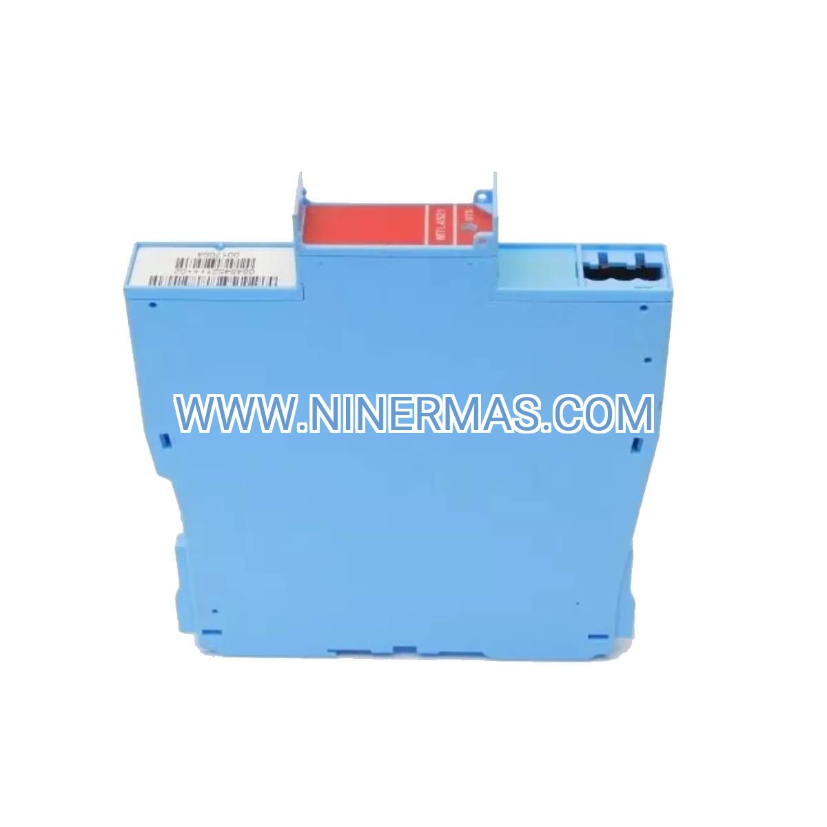
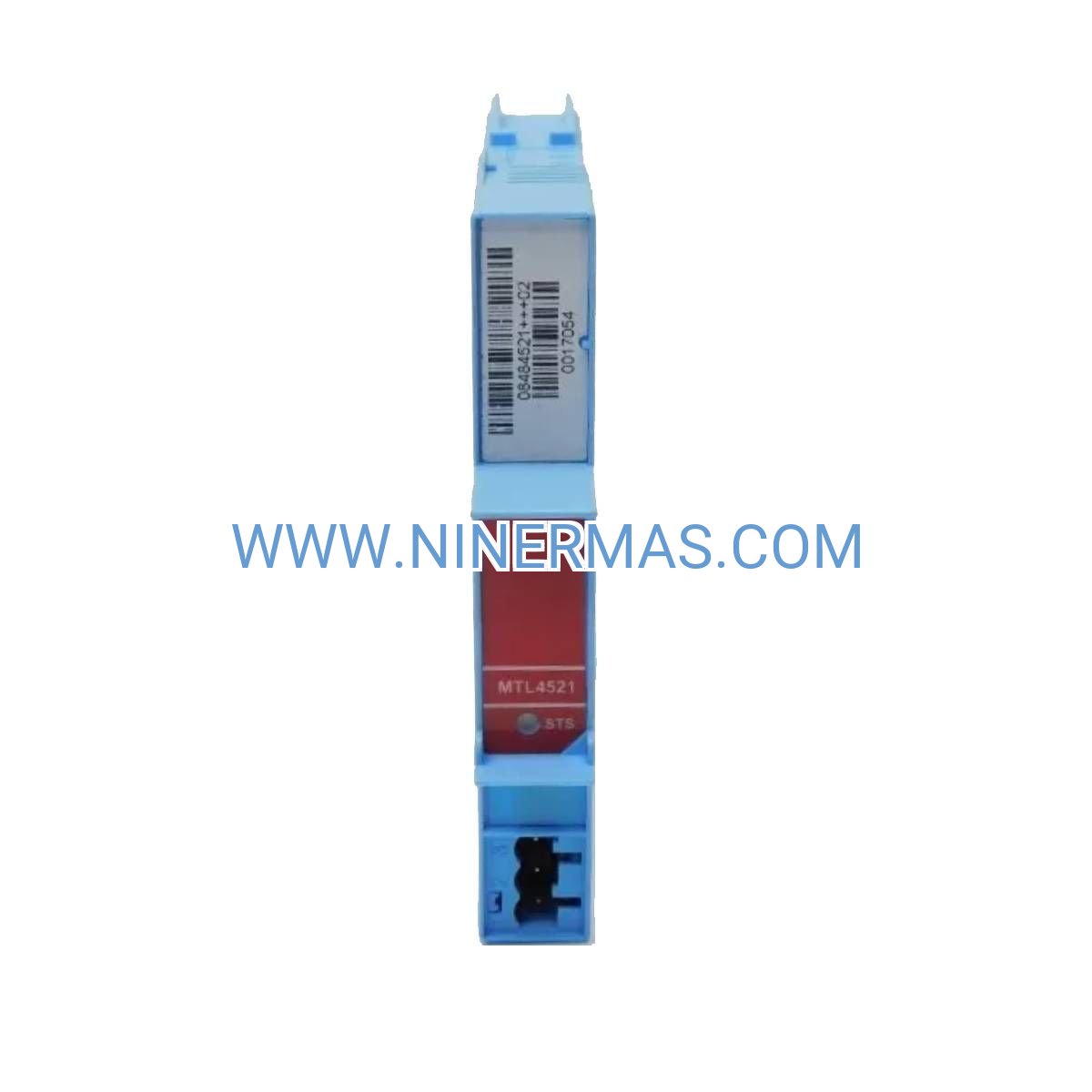
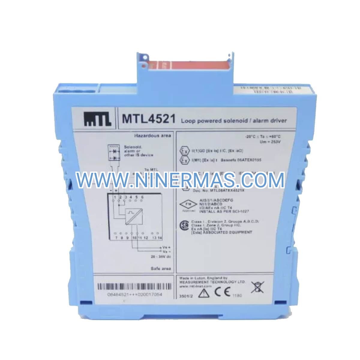
MTL4521 Intrinsic Safety Solenoid Driver (Industrial-Grade Barrier for Hazardous Environments)
The MTL4521 is a high-performance intrinsic safety barrier designed specifically for driving solenoid valves and alarm devices in explosive atmospheres. Through galvanic isolation and energy-limiting circuitry, it delivers reliable 1.2A output current while maintaining intrinsic safety compliance for Zone 0/Division 1 hazardous locations. This barrier enables safe control of field devices from conventional control systems in oil & gas, petrochemical, and chemical processing facilities.
Engineered for applications demanding continuous solenoid actuation in classified areas—including emergency shutdown valves, process control valves, pneumatic actuators, and audible/visual alarms—the MTL4521 addresses critical challenges such as explosion risk mitigation, signal integrity in long cable runs, and protection against electrical faults. It is particularly suited for installations where standard control signals must interface with field equipment located in potentially explosive gas or dust environments.
Certified to ATEX, IECEx, and FM standards with comprehensive agency approvals, the MTL4521 combines proven safety technology with practical installation features. Standard DIN rail mounting, clear terminal identification, and LED status indication facilitate rapid commissioning and ongoing maintenance. Suitable for design engineers, system integrators, instrumentation contractors, and plant maintenance teams. Contact our application engineers for circuit design assistance, loop calculations, and project-specific recommendations.
Core Features & Technical Advantages
High Current Output Capability
Provides up to 1.2A continuous output current to reliably energize industrial solenoid valves and high-current alarm devices, ensuring positive actuation even with voltage drops across extended field wiring or aged solenoid coils.
Comprehensive Intrinsic Safety Protection
Dual-channel energy limitation with fault-tolerant design maintains safety integrity under single-fault conditions. Certified for installation in Zone 0 (Gas Group IIC) and Division 1 environments, meeting the most stringent hazardous area classifications worldwide.
Galvanic Isolation Technology
Transformer-based isolation between safe area and hazardous area circuits eliminates ground loop interference, protects control systems from field faults, and ensures signal integrity in electrically noisy industrial environments.
Robust Environmental Performance
Operating temperature range of -40°C to +60°C with conformal coating protection against humidity, dust, and chemical vapors. IP20 enclosure rating suitable for standard control panel installations with optional IP65 terminal covers available.
Simplified Installation & Diagnostics
Standard 35mm DIN rail mounting with plug-in terminal blocks for tool-free removal during maintenance. Dual-color LED indicators provide instant visual confirmation of power status and output state, reducing commissioning time and troubleshooting effort.
Wide Input Compatibility
Accepts control signals from PLCs, DCS systems, relay outputs, and manual switches. Compatible with both sourcing and sinking logic configurations, offering flexibility for integration with diverse control architectures.
Typical Application Scenarios
The MTL4521 intrinsic safety barrier serves critical control functions across industries where process safety and operational reliability intersect:
Oil & Gas Production and Refining
Controls emergency shutdown (ESD) valves, blowdown valves, and process isolation valves in offshore platforms, wellhead facilities, and refinery process units. Ensures fail-safe operation of safety instrumented systems (SIS) while maintaining Zone 0 compliance in vapor recovery areas and loading terminals.
Chemical and Petrochemical Processing
Drives pneumatic actuators and solenoid pilot valves in reactor control systems, distillation columns, and batch processing equipment. Provides reliable actuation for material transfer valves, vent controls, and emergency depressurization systems in solvent handling and polymer production facilities.
Pharmaceutical Manufacturing
Operates clean-in-place (CIP) valves, sterile transfer systems, and containment isolation valves in classified manufacturing areas. Supports automated batch processes requiring precise valve sequencing while meeting ATEX requirements for solvent-based formulation areas.
Paint and Coatings Production
Controls material feed valves, color change systems, and spray booth isolation in environments with flammable vapor concentrations. Enables automated mixing and dispensing operations while maintaining intrinsic safety in Zone 0 mixing rooms and storage areas.
Grain Handling and Food Processing
Actuates dust collection system valves, bin discharge gates, and pneumatic conveying diverters in facilities handling combustible dust. Provides safe control of material flow in flour mills, feed production, and grain elevators classified for dust explosion hazards.
Technical Specifications & Selection Guide
To ensure optimal performance and compliance, the MTL4521 offers the following standardized parameters suitable for most industrial solenoid control applications:
Electrical Characteristics
- Output Current: 1.2A maximum continuous (intrinsically safe circuit)
- Output Voltage: 24V DC nominal (safe area supply dependent)
- Input Signal: Contact closure, logic level, or voltage-free switch
- Supply Voltage: 20-35V DC (safe area power)
- Power Consumption: Approximately 3W typical
- Isolation Voltage: 250V AC test (safe area to hazardous area)
Safety Approvals & Certifications
- ATEX: II 1 G Ex ia IIC T4 Ga (Zone 0 gas)
- IECEx: Ex ia IIC T4 Ga
- FM/CSA: Class I, Division 1, Groups A, B, C, D
- SIL Capability: Suitable for SIL 2 applications per IEC 61508
Mechanical & Environmental
- Mounting: 35mm DIN rail (EN 50022)
- Enclosure: Polycarbonate housing, IP20 standard (IP65 optional)
- Dimensions: 99mm (H) × 22.5mm (W) × 114mm (D)
- Operating Temperature: -40°C to +60°C
- Storage Temperature: -40°C to +80°C
- Humidity: 0-95% RH non-condensing
- Vibration: IEC 60068-2-6 compliant
Connection & Wiring
- Terminal Type: Screw terminals, 0.2-2.5mm² wire capacity
- Terminal Arrangement: Plug-in removable blocks
- Cable Entry: Side or rear entry configurations
- Maximum Cable Capacitance: 1.0μF (hazardous area circuit)
- Maximum Cable Inductance: 1.0mH (hazardous area circuit)
Selection Considerations
When specifying the MTL4521 for your application, consider the following project-specific factors:
- Solenoid Coil Characteristics: Verify coil resistance, inductance, and voltage rating match barrier output parameters. Typical solenoid valves rated 24V DC with 20-200Ω resistance are compatible.
- Hazardous Area Classification: Confirm gas group (IIA, IIB, IIC) and temperature class requirements. MTL4521 supports IIC (most restrictive) covering hydrogen and acetylene atmospheres.
- Cable Run Distance: Calculate total loop capacitance and inductance including field wiring. For runs exceeding 500 meters, consult entity parameters to verify compliance.
- Control System Interface: Identify whether PLC/DCS outputs are sourcing or sinking type. MTL4521 accepts both configurations with appropriate wiring.
- Environmental Conditions: For outdoor installations or wash-down areas, specify IP65 terminal covers and conformal coating options.
- Redundancy Requirements: For SIL-rated safety functions, implement dual-channel configurations with separate barriers per safety integrity requirements.
For application-specific guidance, provide our engineering team with: hazardous area classification, solenoid specifications (voltage, current, resistance), cable type and length, control system output type, and environmental conditions. We will verify compatibility and recommend optimal installation practices.
Advanced Configuration Options
Multi-Channel Installations
For applications requiring multiple solenoid controls, MTL4521 units can be mounted side-by-side on standard DIN rail with minimal spacing. Shared power supply distribution reduces panel wiring complexity while maintaining individual circuit isolation.
Redundant Safety Systems
In safety instrumented systems (SIS) requiring 1oo2 or 2oo3 voting logic, deploy multiple MTL4521 barriers in parallel configurations. Each barrier drives a separate solenoid valve or redundant coil, ensuring fail-safe operation even with single-component failure.
Remote Monitoring Integration
While the MTL4521 is a passive barrier without built-in diagnostics, output status can be monitored by reading control system feedback or installing current-sensing relays in the safe area circuit. This enables predictive maintenance and fault detection in critical control loops.
Hybrid Control Architectures
Combine MTL4521 barriers with smart positioners, partial stroke test (PST) systems, and digital valve controllers to create intelligent final control elements. The barrier provides intrinsic safety protection while allowing advanced diagnostics and performance monitoring through separate communication channels.
Delivery, Service & Quality Assurance
Lead Time & Availability
Standard MTL4521 units typically ship from stock with 3-5 business day lead time for quantities up to 50 units. Larger project quantities or custom configurations (special terminal markings, extended temperature ratings) require 2-3 weeks. Expedited shipping available for urgent shutdowns or project deadlines.
Warranty & Support
All MTL4521 barriers include a comprehensive 12-month manufacturer warranty covering defects in materials and workmanship. Extended warranty programs available for critical infrastructure applications. Technical support includes pre-sale application engineering, installation guidance, and post-commissioning troubleshooting assistance.
Documentation Package
Each unit ships with complete technical documentation including: installation manual with wiring diagrams, entity parameter certificates for hazardous area compliance, ATEX/IECEx declaration of conformity, and loop calculation worksheets. CAD drawings (DXF/PDF) and 3D models (STEP) available for panel design integration.
Calibration & Testing
Factory calibration certificates traceable to national standards provided upon request. All units undergo 100% functional testing including isolation voltage verification, output current measurement, and safety parameter validation before shipment. Third-party witness testing available for critical projects.
Training & Commissioning
On-site commissioning support and operator training available for large installations or complex safety systems. Remote technical assistance via video call for troubleshooting and configuration verification. Access to online resource library including application notes, case studies, and installation videos.
Frequently Asked Questions (FAQ)
Q: How does the MTL4521 intrinsic safety barrier integrate with existing PLC or DCS control systems?
A: The MTL4521 accepts standard digital output signals from PLCs and DCS systems (both sourcing and sinking types). Connect the safe area terminals to your control system output module, and the hazardous area terminals to the field solenoid. The barrier provides galvanic isolation while passing the switching signal through. Verify your control output can handle the barrier's input impedance (typically 1-2kΩ) and that supply voltage matches requirements (20-35V DC).
Q: What is the maximum number of solenoid valves one MTL4521 barrier can control?
A: Each MTL4521 barrier controls one solenoid valve or device, providing a dedicated 1.2A output channel. For applications requiring multiple valve controls, install one barrier per solenoid. Barriers can share common safe area power supplies and mount adjacently on DIN rail. For manifold valve assemblies with multiple solenoids, calculate total current draw—if individual solenoids require less than 1.2A and can be wired in parallel within entity parameters, a single barrier may suffice, but separate barriers per valve are recommended for diagnostic clarity.
Q: What energy savings or efficiency improvements can be expected with intrinsic safety barriers?
A: Intrinsic safety barriers like the MTL4521 are not primarily energy-saving devices—their function is safety compliance, not efficiency optimization. However, they enable system-level benefits: by allowing standard control systems to interface with hazardous area devices, they eliminate the need for expensive explosion-proof enclosures and conduit systems, reducing installation costs by 30-50%. The barrier itself consumes approximately 3W, negligible compared to overall system power. Energy efficiency comes from optimized process control (precise valve actuation reducing waste) rather than the barrier's electrical characteristics.
Q: What are the installation environment requirements and protection ratings for the MTL4521?
A: The MTL4521 is designed for installation in safe area control panels with IP20 standard protection (finger-safe terminals, suitable for indoor enclosures). Operating temperature range is -40°C to +60°C, accommodating most industrial control room and field cabinet environments. For harsh environments, optional IP65 terminal covers provide protection against dust and water jets. The barrier must be mounted in a safe area (non-hazardous location); only the field wiring extends into the hazardous zone. Ensure adequate ventilation in densely populated panels—allow 10mm spacing between units for heat dissipation.
Q: Does the MTL4521 support remote monitoring, data acquisition, or communication protocols like Modbus or HART?
A: The MTL4521 is a passive intrinsic safety barrier without built-in communication capabilities or digital protocols. It provides electrical isolation and energy limiting for simple on/off solenoid control. For remote monitoring, read the control system's output status (which reflects commanded valve state) or install current-sensing devices in the safe area circuit to detect actual solenoid energization. If your application requires valve position feedback, diagnostics, or smart device communication, consider pairing the MTL4521 with intelligent valve positioners or digital valve controllers that have separate HART or Modbus interfaces—the barrier handles power/control while communication runs through dedicated intrinsically safe communication barriers.
Q: Can the MTL4521 be used in SIL-rated safety instrumented systems, and what documentation is required?
A: Yes, the MTL4521 is suitable for use in Safety Instrumented Systems (SIS) up to SIL 2 per IEC 61508/61511 standards. For SIL applications, request the Safety Manual and Failure Modes, Effects, and Diagnostics Analysis (FMEDA) report, which provide failure rate data (λ values), safe failure fraction (SFF), and architectural constraints. When designing SIL loops, account for the barrier's contribution to overall system probability of failure on demand (PFD). For SIL 3 applications, implement redundant barrier configurations (1oo2 or 2oo3 voting) with diverse solenoid valves. Ensure periodic proof testing per your safety requirements specification—typical test intervals are 12-24 months for SIL 2 loops.
Request Technical Support & Custom Solutions
Our application engineering team is ready to assist with product selection, system design, and compliance verification. To receive detailed specifications, loop calculation worksheets, or project quotations, please provide the following information:
- Project Overview: Application type, industry, and hazardous area classification (Zone/Division, Gas Group, Temperature Class)
- Solenoid Specifications: Manufacturer, model number, coil voltage, current draw, resistance, and inductance
- Field Wiring Details: Cable type, length, number of pairs, and installation routing (conduit, cable tray, direct burial)
- Control System Information: PLC/DCS manufacturer, output module type (sourcing/sinking), and available supply voltages
- Environmental Conditions: Ambient temperature range, humidity, vibration, and enclosure IP rating requirements
- Quantity & Timeline: Number of units required and project commissioning schedule
Our engineers will review your requirements and provide a comprehensive solution including product recommendations, wiring diagrams, entity parameter verification, and compliance documentation. For complex safety systems, we offer on-site commissioning support and operator training to ensure successful project execution.
© 2026 NINERMAS COMPANY LIMITED. All rights reserved.
Original Source: https://ninermas.com
Contact: sale@ninermas.com | +0086 187 5021 5667
Related products

Contact Info
-
Address:22 / F, South Wo Hang building, 148 Wing Lok Street, Sheung Wan, Western District, Hong Kong
-
Phone:+8618750215667
-
Email: