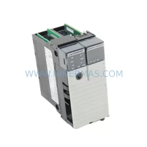
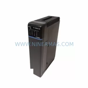
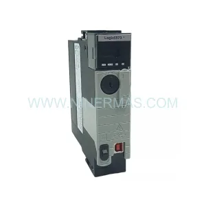
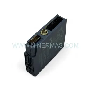
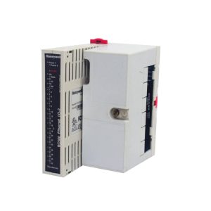
Original Industrial Spare Part
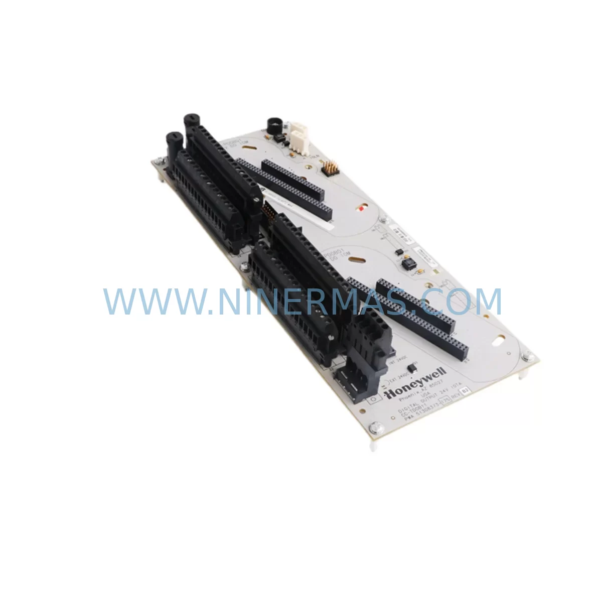
HOLLEYWELL CC-TDOB11 51308373-175 Retrofit Digital Output
Verify the part, confirm the platform family, and move straight into quotation with the right commercial details.
RFQ Ready
- SKUCC-TDOB11 51308373-175
- CategoryPLC & Industrial Automation Modules
- BrandHOLLEYWELL
- SupportAvailability, lead time, condition, and shipping coordination
How Buyers Usually Use This Page
- Confirm the exact part number and platform family before sending the quote request.
- Use direct email when quantity, condition, and destination are already defined internally.
- Switch to the broader brand or category archive when you need alternates nearby.
Series Navigation
Move through the most common platform families behind this part.
Product RFQ
Send this part directly for quotation.
Include quantity, required condition, destination country, and target delivery timing. Current reference: HOLLEYWELL CC-TDOB11 51308373-175 Retrofit Digital Output with SKU CC-TDOB11 51308373-175.
HOLLEYWELL CC-TDOB11 51308373-175 Retrofit-Compatible Digital Output Module for Legacy Systems
The HOLLEYWELL CC-TDOB11 (Part No. 51308373-175) is a 24V DC digital output module engineered for seamless integration into legacy distributed control system (DCS) architectures, particularly those built around IOTA-compatible backplane infrastructure. As industrial facilities face increasing pressure to extend the operational life of aging control platforms while managing capital expenditure, the CC-TDOB11 has become a critical component in retrofit projects, discontinued spare part replacement programs, and phased system modernization strategies across process industries including oil and gas, chemical processing, power generation, and water treatment.
When a plant’s original digital output module reaches end-of-life or becomes unavailable through the OEM supply chain, the CC-TDOB11 provides a verified drop-in replacement path that preserves existing wiring infrastructure, backplane slot assignments, and controller logic without requiring a full panel redesign. Engineers undertaking a retrofit must carefully confirm several parameters before installation: the module’s 24V DC output voltage rating must match the field device load requirements; terminal block wiring assignments must be cross-referenced against the original I/O drawing set; the backplane interface connector must align with the IOTA carrier card installed in the existing rack; and the module address configured in the DCS controller must be re-mapped if the replacement occupies a different physical slot position.
Program compatibility is another key consideration. Before swapping the CC-TDOB11 into service, the site automation engineer should verify that the existing controller logic — whether running on a Honeywell C300 controller, an Experion PKS node, or a legacy LCN/UCN platform — correctly references the I/O point addresses associated with this module. In many retrofit scenarios, the original HMI display graphics reference specific tagnames tied to the outgoing module’s channel assignments; these tagnames must be validated and, if necessary, remapped in the HMI configuration to ensure operator displays remain accurate after the swap.
Communication link integrity is equally important. In systems where the CC-TDOB11 interfaces with a FIM4 (Field Interface Module) or a similar communication gateway, the fieldbus segment must be checked for address conflicts before the new module is brought online. If the retrofit involves migrating from an older serial-based communication protocol to a modern Ethernet-based architecture, additional protocol conversion hardware may be required to bridge the legacy backplane to the new network infrastructure.
Installation space confirmation is a practical step that is often overlooked in planning. The CC-TDOB11 occupies a standard IOTA module slot, but engineers should verify rack density and available slot count, particularly in control cabinets where I/O expansion has been added incrementally over the years. In some cases, an I/O expansion chassis or an additional IOTA carrier may be required to accommodate the replacement module alongside newly added signal isolation modules or marshalling terminal assemblies.
Upgrade Compatibility Table
| Parameter | CC-TDOB11 51308373-175 | Retrofit Notes |
|---|---|---|
| Output Voltage | 24V DC | Confirm field device load voltage before installation |
| Module Form Factor | IOTA-compatible plug-in module | Verify IOTA carrier card type and slot availability in existing rack |
| Backplane Interface | Standard IOTA backplane connector | Check backplane revision; confirm connector pin compatibility |
| Communication Compatibility | Compatible with FIM4 and legacy DCS fieldbus segments | Validate fieldbus address assignment; check for address conflicts |
| Controller Compatibility | Honeywell C300, Experion PKS, LCN/UCN platforms | Re-map I/O point addresses in controller logic if slot position changes |
| HMI Integration | Tagname-based point referencing | Validate HMI display tagnames after module swap; update graphics if required |
| Installation Space | Single IOTA slot | Confirm rack slot availability; assess need for expansion chassis |
| Replacement Scope | Drop-in replacement for discontinued digital output modules | Cross-reference original part number against CC-TDOB11 specification sheet |
| Commissioning Requirement | Field loop check and point-by-point I/O verification | Perform output forcing test before returning to automatic control |
| Warranty | 12-Month Warranty | Covers manufacturing defects; includes pre-shipment functional test |
Retrofit Planning for Existing Automation Systems
A successful retrofit using the CC-TDOB11 begins well before the module arrives on site. The project engineer should compile a complete bill of materials for the affected control cabinet, identifying every component that interfaces with the outgoing digital output module. In a typical Honeywell Experion PKS or TDC 3000 environment, this means accounting for the IOTA carrier card that physically seats the module, the associated terminal board that connects field wiring, and the FIM4 communication module that bridges the I/O subsystem to the controller highway.
Signal isolation is a common requirement in older installations where field wiring runs long distances or passes through electrically noisy environments. Before finalizing the retrofit plan, the engineer should assess whether the existing signal isolators or signal conditioners installed in the marshalling cabinet are still rated for the output characteristics of the CC-TDOB11. In some cases, replacing the digital output module also triggers a review of the associated power supply module, since the new module’s inrush current profile may differ slightly from the original unit.
Wiring adaptation is another area requiring careful attention. The CC-TDOB11’s terminal block layout should be compared against the original module’s wiring diagram. If the terminal numbering differs, a wiring adapter or a revised termination drawing must be prepared before the cutover. In facilities where the original I/O drawings are incomplete or outdated, a field survey of the existing terminations is strongly recommended prior to ordering replacement parts.
For sites planning a broader migration — for example, moving from a legacy serial communication architecture to a modern Ethernet-based control network — the CC-TDOB11 can serve as a stable interim solution while the higher-level communication infrastructure is upgraded. During this transition period, the module continues to operate on the existing backplane while new communication gateways, such as updated FIM modules or Ethernet interface cards, are installed in parallel. This phased approach allows the plant to maintain continuous production while progressively modernizing the control system architecture.
Rack and chassis planning should also include a review of available expansion slots. In control rooms where I/O density has grown over the years through incremental additions of analog input modules, thermocouple input modules, and relay output modules, the available slot count in the original chassis may be limited. If no free slot is available adjacent to the existing digital output position, an IOTA expansion chassis may need to be added to the cabinet, along with the associated power distribution and grounding provisions.
Finally, the retrofit plan should include a pre-shipment test report for the CC-TDOB11. NINERMAS performs functional verification on each unit before dispatch, confirming output channel operation, voltage levels, and communication handshake with a compatible controller. This pre-shipment test reduces the risk of discovering a defective module during a planned maintenance window, which is particularly important in facilities where the next available shutdown opportunity may be months away.
Downtime Control During System Migration
Minimizing unplanned downtime is the primary concern for any plant engineer undertaking a digital output module replacement on a live production system. The CC-TDOB11 retrofit strategy is designed to support a controlled, low-risk cutover process that protects the integrity of the existing control program and maintains field device continuity throughout the transition.
The recommended approach begins with a pre-cutover simulation: before removing the original module, the engineer should place the affected control loops in manual mode at the DCS operator station, ensuring that field devices — valves, actuators, motor starters, and solenoids — remain in their last commanded state during the swap. This prevents unintended process upsets caused by output channel de-energization during the module exchange.
Once the original module is removed and the CC-TDOB11 is seated in the IOTA carrier, the engineer should perform a point-by-point output forcing test before returning any loop to automatic control. This involves commanding each output channel from the DCS engineering workstation and verifying the corresponding field device response at the terminal board. Any discrepancy in channel assignment or output polarity should be resolved before the loop is released to automatic operation.
Controller logic protection is equally important. The existing ladder logic or function block program stored in the C300 controller or equivalent platform should be backed up to the engineering workstation before the cutover begins. If the module address changes as a result of the slot reassignment, the controller configuration must be updated and downloaded to the controller before the new module is commissioned. A configuration mismatch between the controller’s I/O map and the physical module position will result in communication faults that prevent the module from operating correctly.
HMI continuity should also be verified as part of the post-installation checklist. After the CC-TDOB11 is online and communicating with the controller, the operator should confirm that all associated HMI display points are updating correctly and that alarm setpoints remain intact. In systems where the HMI is connected to the DCS via an OPC server or a dedicated data highway, a brief communication test between the HMI station and the controller is recommended to confirm end-to-end data integrity.
With proper planning, the physical module swap can typically be completed within a single four-hour maintenance window, with pre-cutover preparation and post-installation verification accounting for the majority of the elapsed time. NINERMAS’s technical support team is available to assist with pre-installation planning, wiring verification, and post-commissioning troubleshooting to help keep the cutover on schedule.
Retrofit Support FAQ
Q1: Is the CC-TDOB11 51308373-175 a direct drop-in replacement for the original discontinued module?
A: The CC-TDOB11 is designed as a retrofit-compatible replacement for legacy IOTA-based digital output modules operating at 24V DC. Before installation, engineers should verify the IOTA carrier card type, terminal block wiring layout, and controller I/O address assignment to confirm full compatibility with the specific system configuration at their site.
Q2: What commissioning steps are required after installing the CC-TDOB11?
A: After seating the module in the IOTA carrier, perform a point-by-point output forcing test from the DCS engineering workstation to verify each channel’s operation. Confirm that the controller I/O map correctly references the module’s slot address, check HMI display tagname assignments, and verify communication link status on the FIM4 or equivalent fieldbus interface module before returning loops to automatic control.
Q3: Does NINERMAS provide pre-shipment testing and what does the 12-month warranty cover?
A: Yes. Each CC-TDOB11 unit undergoes functional verification before dispatch, including output channel operation testing and communication handshake confirmation. The 12-month warranty covers manufacturing defects and component failures under normal operating conditions. It does not cover damage resulting from incorrect installation, overvoltage conditions, or environmental factors outside the module’s rated operating range.
Q4: What is the typical lead time and stock availability for the CC-TDOB11 51308373-175?
A: NINERMAS maintains inventory of the CC-TDOB11 to support urgent retrofit and emergency replacement requirements. Standard orders are processed and dispatched within 3–5 business days. For large-quantity orders or projects requiring multiple units across an extended delivery schedule, please contact our sales team to confirm current stock levels and arrange a dedicated supply allocation.
| Product Series | Other series |
|---|
Catalog Continuation
More HOLLEYWELL modules in the catalog.
Use the brand lane to compare nearby part numbers, platform-adjacent modules, and other inquiry-ready listings before sending your final RFQ.
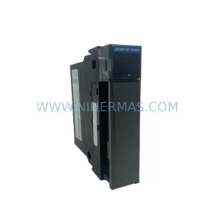
SKU: C-PPD011 51309241-125
HOLLEYWELL C-PPD011 51309241-125 Service-Ready Spare Part
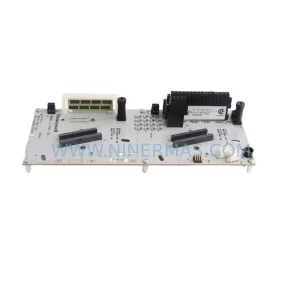
SKU: CC-TAIX11 51308365-175
HOLLEYWELL CC-TAIX11 51308365-175 Service-Ready Spare Part
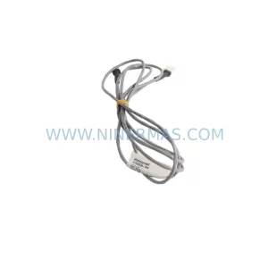
SKU: I/O Link Cable
HOLLEYWELL 51202330-200 Retrofit-Compatible I/O Link Cable
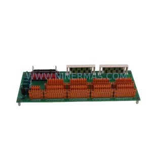
SKU: MC-TDIY22 51204160-175
HOLLEYWELL MC-TDIY22 51204160-175 Service-Ready Spare Part
Catalog Continuation
Alternative parts within PLC & Industrial Automation Modules.
Stay inside the same system family when you need substitutes, adjacent modules, or a broader shortlist for procurement review.
SKU: DIA 27CM 0020-21422 ARIES ACR CP*AR-13CE-15122 LAM 796-901039-002 100018066
AMAT 796-901039-002 Retrofit-Compatible Clamp for Legacy Systems