Original Industrial Spare Part
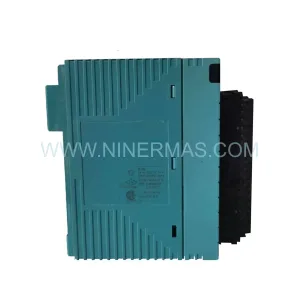
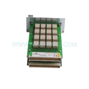
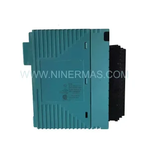
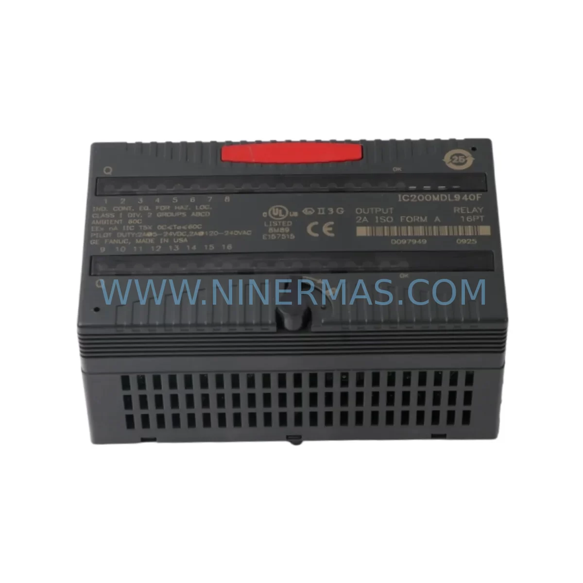
GE IC200MDL940F Retrofit-Compatible Relay Output Module
Verify the part, confirm the platform family, and move straight into quotation with the right commercial details.
RFQ Ready
- SKUIC200MDL940F
- CategoryPLC & Industrial Automation Modules
- BrandGE
- SupportAvailability, lead time, condition, and shipping coordination
How Buyers Usually Use This Page
- Confirm the exact part number and platform family before sending the quote request.
- Use direct email when quantity, condition, and destination are already defined internally.
- Switch to the broader brand or category archive when you need alternates nearby.
Series Navigation
Move through the most common platform families behind this part.
Product RFQ
Send this part directly for quotation.
Include quantity, required condition, destination country, and target delivery timing. Current reference: GE IC200MDL940F Retrofit-Compatible Relay Output Module with SKU IC200MDL940F.
GE IC200MDL940F Retrofit-Compatible Relay Output Module for Legacy Systems
The GE IC200MDL940F is a relay output module designed for the GE VersaMax distributed I/O platform, widely deployed across manufacturing, utilities, and process control facilities. As legacy GE Series 90 and VersaMax systems approach end-of-life, the IC200MDL940F remains a critical component for engineers managing brownfield retrofits, control cabinet upgrades, and spare parts lifecycle extension. Whether you are replacing a failed module in an aging production line or planning a phased migration to a modern control architecture, the IC200MDL940F provides a direct, drop-in compatible solution that minimizes engineering rework and reduces unplanned downtime.
At NINERMAS, every IC200MDL940F unit is sourced from verified supply channels, inspected prior to shipment, and backed by a 12-month warranty. We maintain ready stock to support urgent replacement orders and long-term MRO procurement programs.
Upgrade Compatibility Table
| Parameter | IC200MDL940F Specification | Retrofit / Upgrade Notes |
|---|---|---|
| Module Type | Relay Output, 8-point | Direct replacement for IC200MDL940 (non-F suffix); verify firmware revision compatibility |
| Output Voltage Range | 5–250V AC / 5–30V DC | Confirm field device voltage ratings before wiring; no additional relay interposing required in most applications |
| Output Current per Point | 2A resistive | Verify load current against existing terminal block wiring; replace undersized conductors if upgrading from older 1A-rated modules |
| Backplane Interface | VersaMax I/O backplane (IC200CHS series) | Compatible with IC200CHS002, IC200CHS005, IC200CHS014 carriers; confirm slot assignment in programmer |
| Communication Compatibility | Profibus DP, Ethernet (via NIU) | Works with IC200PBI001 Profibus NIU and IC200ETM001 Ethernet NIU; no protocol reconfiguration needed for like-for-like swap |
| Installation Footprint | Standard VersaMax single-slot | No panel modification required; fits existing DIN rail and cabinet cutouts |
| Programming Environment | Proficy Machine Edition (ME) | Existing ladder logic and I/O mapping remain valid; re-download program after module swap to confirm I/O table |
| Warranty | 12 Months — covers manufacturing defects; includes pre-shipment functional test report on request | |
Retrofit Planning for Existing Automation Systems
Successful integration of the IC200MDL940F into an existing control system requires a structured pre-retrofit assessment. Begin by auditing the current VersaMax rack configuration: document each occupied slot, the module type installed, and the I/O addresses assigned in the Proficy Machine Edition hardware configuration. The IC200MDL940F occupies a single slot on the IC200CHS series carrier and draws power from the local bus supplied by the IC200PWR002 or IC200PWR101 power supply module. Before pulling the failed module, confirm that the power supply has sufficient headroom to support the replacement — relay output modules have a higher inrush current profile than transistor output equivalents, and an undersized IC200PWR002 may trip under load if the cabinet has been expanded since original commissioning.
Terminal block wiring on the IC200MDL940F follows the standard VersaMax field-side connector pinout. If the existing installation uses the removable terminal block (RTB) style connector, the wiring harness can be transferred directly to the new module without re-termination, significantly reducing installation time and the risk of wiring errors. For installations using hardwired terminal strips, prepare a point-to-point wiring diagram from the original engineering drawings before beginning work.
In distributed I/O architectures where the VersaMax rack communicates over Profibus DP via an IC200PBI001 network interface unit, the module address is determined by the slot position on the backplane — not by a physical DIP switch or rotary dial. This means the IC200MDL940F will inherit the I/O address of the module it replaces without any additional configuration, provided it is installed in the same slot. For systems using the IC200ETM001 Ethernet NIU, verify the IP address assignment and confirm that the PLC CPU — typically a GE PACSystems RX3i or a legacy Series 90-30 acting as a remote master — can re-establish communication after the module swap.
Where the retrofit involves migrating from an older GE Series 90-30 discrete output module to the VersaMax IC200MDL940F as part of a broader control cabinet modernization, engineers should also review the HMI screen tag database. SCADA and HMI systems connected via GE SRTP or Modbus TCP may reference output coil addresses that need to be remapped if the I/O base address changes during the migration. Coordinate with the HMI programmer to update any affected faceplate or alarm logic before the cutover window.
For projects involving I/O expansion — adding new relay output points to an existing VersaMax node — the IC200MDL940F can be added to an available slot on the IC200CHS014 expansion carrier. Ensure the IC200PWR002 power budget is recalculated to include the new module’s bus current draw. If the existing carrier is fully populated, a second carrier linked via the IC200CBL105 expansion cable may be required. Signal isolation between the new relay outputs and existing analog input modules such as the IC200ALG320 should be verified to prevent ground loop interference in mixed-signal cabinets.
Downtime Control During System Migration
Minimizing production downtime during a relay output module replacement is achievable with disciplined pre-work. The most effective strategy is to complete all preparatory steps — hardware procurement, wiring documentation review, spare RTB preparation, and Proficy ME project backup — before the maintenance window begins. A like-for-like swap of the IC200MDL940F in a VersaMax rack typically takes under 30 minutes for an experienced technician, provided the replacement module has been pre-tested and the terminal block wiring is documented.
Before removing the existing module, force all relay outputs to the safe de-energized state through the PLC program or via the Proficy ME online forcing function. This prevents uncontrolled actuator movement during the swap. After installing the IC200MDL940F, perform a controlled re-download of the hardware configuration to confirm the module is recognized by the NIU and that all I/O points report correctly in the online I/O status table. Do not restore automatic control until each output point has been individually verified against the field device it drives.
For critical processes where even a brief interruption is unacceptable, consider a parallel wiring strategy: install the new IC200MDL940F in an adjacent slot with temporary wiring, verify its operation under program control, then transfer the field wiring point-by-point during a brief hold. This approach preserves the original program logic and HMI tag mapping while allowing the new module to be validated before the old one is removed. NINERMAS can provide pre-shipment functional test documentation to support your site acceptance procedure and reduce on-site commissioning time.
Retrofit Support FAQ
Q1: Is the IC200MDL940F a direct replacement for the IC200MDL940 (without the F suffix)?
In most applications, yes. The F suffix denotes a conformal-coated version for harsh environment protection. The electrical and mechanical specifications are identical. Verify your application environment and confirm with your engineering team whether the coating is required for your installation.
Q2: What commissioning steps are required after installing the IC200MDL940F?
After physical installation, re-download the Proficy Machine Edition hardware configuration to the NIU or CPU. Verify that the module appears online with no fault indicators. Use the I/O forcing function to test each relay output point individually against the connected field device. Confirm that all HMI tags and SCADA addresses associated with the affected outputs are responding correctly before returning the system to automatic operation.
Q3: Can the IC200MDL940F be used in a mixed rack alongside analog modules such as the IC200ALG320?
Yes. The VersaMax backplane supports mixed module types in the same carrier. Ensure adequate separation between relay output wiring and analog signal wiring to minimize electrical noise. Use shielded cable for analog inputs and ground the shield at one end only. Review the power supply budget to confirm the IC200PWR002 or IC200PWR101 can support the combined bus current of all installed modules.
Q4: What warranty and supply assurance does NINERMAS provide?
All IC200MDL940F units supplied by NINERMAS carry a 12-month warranty covering manufacturing defects and functional failures under normal operating conditions. Pre-shipment testing is performed on every unit, and a functional test report is available on request. We maintain inventory stock to support both urgent single-unit replacement orders and scheduled MRO procurement. Contact our team at sale@ninermas.com or +0086 187 5021 5667 for availability and lead time confirmation.
| Product Series | VersaMax |
|---|---|
| Country of Origin | US |
Catalog Continuation
Nearby part numbers around IC200MDL.
Use this lane when the buyer is comparing adjacent model numbers, revision-near items, or closely related spare variants within the same brand family.
Catalog Continuation
More GE modules in the catalog.
Use the brand lane to compare nearby part numbers, platform-adjacent modules, and other inquiry-ready listings before sending your final RFQ.
Catalog Continuation
Alternative parts within PLC & Industrial Automation Modules.
Stay inside the same system family when you need substitutes, adjacent modules, or a broader shortlist for procurement review.
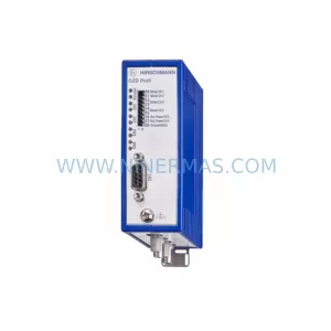
SKU: OZDPROFI12MG12
Hirschmann OZDPROFI12MG12 Spare Part for Industrial Maintenance
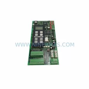
SKU: 07025-0000-70-1-04
KONTRON 07025-0000-70-1-04 Service-Ready Spare Part