Original Industrial Spare Part
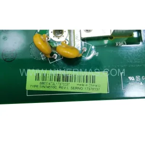
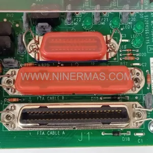
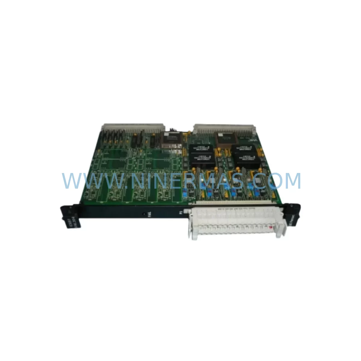
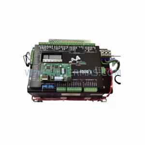
GE Fanuc IC697VDD100 Retrofit-Compatible Discrete Output Module
Verify the part, confirm the platform family, and move straight into quotation with the right commercial details.
RFQ Ready
- SKUIC697VDD100
- CategoryDCS Distributed Control Systems
- BrandGE Fanuc
- SupportAvailability, lead time, condition, and shipping coordination
How Buyers Usually Use This Page
- Confirm the exact part number and platform family before sending the quote request.
- Use direct email when quantity, condition, and destination are already defined internally.
- Switch to the broader brand or category archive when you need alternates nearby.
Series Navigation
Move through the most common platform families behind this part.
Product RFQ
Send this part directly for quotation.
Include quantity, required condition, destination country, and target delivery timing. Current reference: GE Fanuc IC697VDD100 Retrofit-Compatible Discrete Output Module with SKU IC697VDD100.
GE Fanuc IC697VDD100 Retrofit-Compatible Discrete Output Module: Legacy System Compatibility & Smooth Upgrade
The GE Fanuc IC697VDD100 is a discrete output module designed for the GE Series 90-70 PLC platform — one of the most widely deployed industrial control architectures in process manufacturing, power generation, automotive assembly, and heavy industry. As the Series 90-70 platform enters its end-of-life phase, facilities running legacy control cabinets face increasing pressure to source reliable replacement modules, retrofit aging I/O racks, and plan controlled migrations to modern control systems without disrupting production continuity.
NINERMAS maintains verified inventory of the IC697VDD100 to support engineers and maintenance teams managing discontinued spare parts, unplanned downtime events, and long-cycle retrofit projects. Every unit is functionally tested prior to shipment and backed by a 12-month warranty.
Upgrade Compatibility Table
| Parameter | IC697VDD100 Specification | Retrofit / Upgrade Notes |
|---|---|---|
| Platform | GE Series 90-70 | Compatible with IC697 rack and backplane architecture |
| Module Type | Discrete Output (DC) | Verify output voltage and current rating against field wiring |
| Backplane Interface | Series 90-70 VME-based backplane | Confirm slot assignment and rack model (IC697CHS750, IC697CHS782, etc.) |
| Installation | Slide-in module, front-access wiring | Check terminal block compatibility; reuse existing field wiring where possible |
| Communication | Local I/O via backplane; compatible with IC697CPU771, IC697CPU781 and similar CPUs | No protocol change required for direct slot replacement |
| Address Configuration | Configured via Logicmaster 90 or Proficy Machine Edition | Verify %Q address mapping before hot-swap or cold replacement |
| Program Compatibility | Ladder logic references %Q discrete output bits | No program modification required for same-slot replacement |
| HMI Integration | Tag-based via CIMPLICITY or iFIX SCADA | Confirm output tag addresses remain unchanged post-replacement |
| Power Requirement | Supplied via backplane from IC697PWR710 or IC697PWR724 power supply | Verify PSU capacity before adding or replacing output modules |
| Warranty | 12-Month Warranty — All units tested before shipment | |
Retrofit Planning for Existing Automation Systems
Replacing the IC697VDD100 in an active production environment requires careful pre-engineering to avoid configuration errors, wiring faults, or unintended output activation. The following considerations apply to most Series 90-70 retrofit scenarios:
Power Budget Verification: Before installing a replacement IC697VDD100, confirm that the rack’s power supply — typically an IC697PWR710 or IC697PWR724 — has sufficient capacity to support the full module complement. Adding or replacing output modules without checking the power budget is a common cause of intermittent faults in aging control cabinets.
Backplane and Rack Integrity: The IC697VDD100 seats into the Series 90-70 VME backplane. Inspect the rack — whether an IC697CHS750 (5-slot) or IC697CHS782 (9-slot) — for backplane connector damage, corrosion, or bent pins before inserting the replacement module. A damaged backplane can cause the new module to fault immediately or produce erratic output behavior.
Terminal Block and Field Wiring: The IC697VDD100 uses a removable terminal block for field wiring connections. During replacement, document all wire terminations before disconnecting. Label each conductor by %Q address reference to simplify reconnection and reduce the risk of miswiring. Where field wiring has aged or insulation has degraded, this retrofit is an appropriate time to replace conductors and update the wiring schedule.
CPU and I/O Configuration: The Series 90-70 CPU — such as the IC697CPU771, IC697CPU781, or IC697CPU789 — maintains the I/O configuration table that maps physical module slots to program %Q references. After replacing the IC697VDD100, verify that the hardware configuration in Proficy Machine Edition or Logicmaster 90 matches the physical slot assignment. A mismatch will result in a configuration fault and prevent the CPU from entering RUN mode.
Communication Module Continuity: In distributed control architectures, the Series 90-70 rack may include an IC697CMM711 or IC697CMM742 communications module linking the PLC to a DCS, SCADA, or remote I/O network. Confirm that replacing the output module does not interrupt the communication link or require a rack power cycle that would drop the network connection.
Signal Isolation and Analog I/O: In mixed-signal control cabinets, the IC697VDD100 may operate alongside analog input modules such as the IC697ALG230 or signal isolators used to condition 4–20 mA process signals. Ensure that discrete output switching transients do not introduce noise into adjacent analog channels — particularly in cabinets where signal isolation has not been upgraded.
HMI Screen Validation: After replacement, cycle through all CIMPLICITY or iFIX HMI screens that reference outputs controlled by the IC697VDD100. Confirm that output status indicators, interlock displays, and alarm conditions reflect actual field device states. A replacement module that is correctly wired but incorrectly addressed will produce misleading HMI indications without triggering a PLC fault.
Programming Cable and Backup: Before any module replacement, connect a programming cable — such as the IC690ACC901 serial programming cable or a USB-to-serial adapter configured for SNP protocol — and create a full program backup. Store the backup offline. This ensures that if the CPU loses its program during a power interruption, the logic can be restored without delay.
Spare Parts Lifecycle Planning: The IC697VDD100 is a discontinued module. Facilities that rely on Series 90-70 hardware should conduct a spare parts audit covering all installed I/O modules, CPU boards, power supplies, and communication modules. Identifying critical single points of failure — such as the sole CPU or the only available power supply — allows procurement teams to secure buffer stock before availability becomes critical.
Downtime Control During System Migration
Minimizing production interruption during a Series 90-70 module replacement or full system migration requires a structured approach that protects existing program logic, maintains field control continuity, and reduces the window of exposure to uncontrolled process states.
Pre-Replacement Staging: Configure and bench-test the replacement IC697VDD100 before the scheduled maintenance window. Where possible, pre-load the hardware configuration into a spare CPU and verify that the module is recognized without faults. This eliminates configuration troubleshooting from the critical path during the live replacement.
Controlled Output State Management: Before removing the faulted or end-of-life IC697VDD100, place the CPU in STOP mode and confirm that all field devices controlled by the module’s outputs are in a safe state. For processes where output de-energization causes a hazardous condition — such as fail-open valves or de-energized motor contactors — coordinate with operations to establish manual control or process hold conditions before proceeding.
Program Logic Preservation: The Series 90-70 CPU retains its program in battery-backed RAM. Verify that the CPU battery — typically a lithium cell mounted on the IC697CPU board — is functional before beginning the replacement. A failed battery combined with a power interruption during module swap will result in program loss. Replace the battery as part of the retrofit if its age or voltage is uncertain.
Phased Migration Strategy: For facilities planning a full migration from Series 90-70 to a modern platform — such as GE Automation’s PACSystems RX7i or a third-party equivalent — a phased approach that replaces I/O modules incrementally while retaining the existing CPU and backplane reduces risk compared to a full cutover. The IC697VDD100 replacement can serve as a stabilization step that extends the operational life of the existing system while the migration is planned and budgeted.
Post-Replacement Verification: After installing the IC697VDD100 and restoring power, place the CPU in RUN mode and verify each output point individually using the programming terminal’s force function or a structured I/O test routine. Document the test results and update the maintenance record before returning the system to automatic control.
Retrofit Support FAQ
Q: Is the IC697VDD100 a direct drop-in replacement for the existing module in my Series 90-70 rack?
A: Yes, for same-slot replacement in a compatible Series 90-70 rack, the IC697VDD100 is a direct substitution. No program modification is required provided the slot assignment and %Q address mapping remain unchanged. Verify the hardware configuration in your programming software matches the physical installation before returning the CPU to RUN mode.
Q: What pre-shipment testing does NINERMAS perform on the IC697VDD100?
A: Each IC697VDD100 unit is functionally tested prior to shipment to verify output switching, backplane communication, and module self-diagnostics. Units are shipped with a 12-month warranty covering manufacturing defects and functional failures under normal operating conditions.
Q: How do I verify that my rack’s power supply can support the IC697VDD100?
A: Consult the GE Series 90-70 Hardware Reference Manual for the power consumption specification of the IC697VDD100 and sum the load of all modules installed in the rack. Compare the total against the rated output of your IC697PWR710 or IC697PWR724 power supply. If the margin is less than 10–15%, consider upgrading the power supply as part of the retrofit.
Q: Can NINERMAS supply other Series 90-70 modules needed for a broader retrofit project?
A: Yes. NINERMAS maintains inventory of a range of GE Series 90-70 components including CPU modules, power supplies, analog and discrete I/O modules, and communication modules. Contact our team at sale@ninermas.com or +0086 187 5021 5667 to discuss your project requirements and confirm current stock availability.
—
| Product Series | Fanuc |
|---|---|
| Country of Origin | US |
Catalog Continuation
More GE Fanuc modules in the catalog.
Use the brand lane to compare nearby part numbers, platform-adjacent modules, and other inquiry-ready listings before sending your final RFQ.
Catalog Continuation
Alternative parts within DCS Distributed Control Systems.
Stay inside the same system family when you need substitutes, adjacent modules, or a broader shortlist for procurement review.