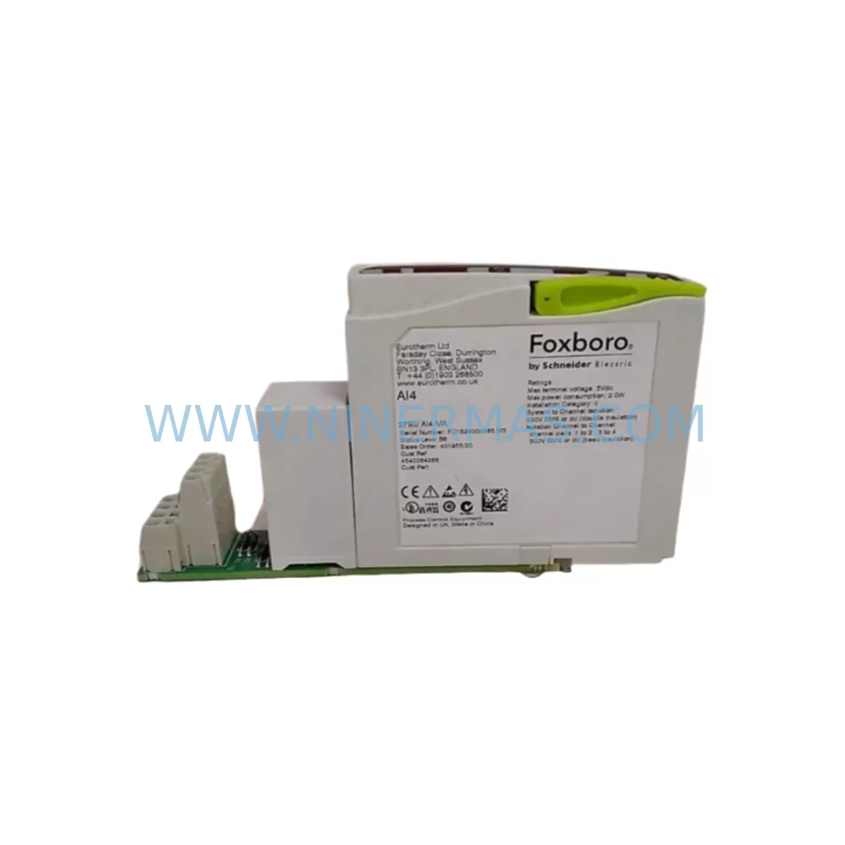
Original Industrial Spare Part
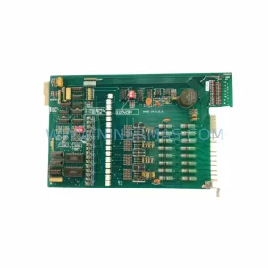
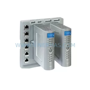
Foxboro 2750/DO4 Service-Ready Spare Part for Industrial Maintenance
Verify the part, confirm the platform family, and move straight into quotation with the right commercial details.
RFQ Ready
- SKU2750/DO4
- CategoryDCS Distributed Control Systems
- BrandFOXBORO
- SupportAvailability, lead time, condition, and shipping coordination
How Buyers Usually Use This Page
- Confirm the exact part number and platform family before sending the quote request.
- Use direct email when quantity, condition, and destination are already defined internally.
- Switch to the broader brand or category archive when you need alternates nearby.
Series Navigation
Move through the most common platform families behind this part.
Product RFQ
Send this part directly for quotation.
Include quantity, required condition, destination country, and target delivery timing. Current reference: Foxboro 2750/DO4 Service-Ready Spare Part for Industrial Maintenance with SKU 2750/DO4.
Foxboro 2750/DO4 Service-Ready Spare Part for Industrial Maintenance
The Foxboro 2750/DO4 is a digital output module designed for the Foxboro 2750 Series distributed control system, widely deployed across oil & gas, petrochemical, power generation, and continuous process manufacturing facilities. As aging DCS infrastructure enters its extended lifecycle phase, maintaining a verified stock of service-ready spare parts such as the 2750/DO4 is a critical element of any plant maintenance strategy. Unplanned downtime caused by a failed digital output module can halt an entire production line within minutes — having a pre-tested, warranty-backed replacement on the shelf is the most effective insurance against that risk.
The 2750/DO4 provides discrete output channels that interface directly with field devices including solenoid valves, motor starters, relay coils, and indicator lamps. Its role in the control loop makes it a high-priority spare: when this module fails, the controller loses the ability to command field actuators, resulting in a loss of automatic control and forcing operators into manual override mode. Rapid replacement with a verified 2750/DO4 spare restores normal operation and eliminates the extended downtime associated with emergency procurement from the open market.
At NINERMAS, every Foxboro 2750/DO4 unit undergoes pre-shipment functional testing to confirm output channel integrity, backplane communication, and LED status indication before dispatch. Each unit ships with a 12-month warranty covering manufacturing defects and functional failures under normal operating conditions. Our inventory is maintained to support both immediate emergency replacement orders and long-term planned maintenance programs.
Spare Maintenance Table
| Parameter | Specification / Detail |
|---|---|
| Part Number | 2750/DO4 |
| Brand | Foxboro |
| Series | Foxboro 2750 Series DCS |
| Module Type | Digital Output Module |
| Output Channels | 4 discrete output channels (DO) |
| Output Signal Type | Discrete / Digital (24 VDC typical) |
| Backplane Interface | 2750 Series carrier/backplane compatible |
| Field Device Compatibility | Solenoid valves, relay coils, motor starters, indicator lamps |
| Installation | Plug-in module, carrier-mounted, hot-swap capable (system dependent) |
| Application Environment | Industrial process control — oil & gas, petrochemical, power, chemical |
| Condition | Original / Service-Ready |
| Pre-Shipment Testing | Functional output channel test, backplane communication verification |
| Warranty | 12 Months |
| Origin | United States |
| Lead Time | In-stock — typically ships within 2–5 business days |
| Long-Term Supply | Available for blanket order and scheduled spare parts programs |
Maintenance Planning for Continuous Operation
Replacing the Foxboro 2750/DO4 in a live control environment requires a structured approach to minimize exposure and confirm system integrity before returning the loop to automatic control. Maintenance engineers should treat a 2750/DO4 replacement as part of a broader cabinet inspection, not an isolated swap. The following associated components and subsystems should be evaluated concurrently to prevent repeat failures and ensure the restored loop performs reliably.
Begin with the 2750 Series carrier or baseplate that houses the DO4 module. Inspect the backplane connector pins for corrosion, mechanical damage, or contamination — a degraded carrier can cause intermittent output faults even after a module replacement. If the carrier shows wear, schedule its replacement during the next planned outage window.
Verify the 24 VDC field power supply feeding the output channels. A marginal or failing power supply is a common root cause of digital output module failures and will damage a replacement module if not corrected. Check voltage under load and inspect the supply’s capacitors and fuse protection. The Foxboro 2750/PS1 or equivalent series power supply module should be included in your cabinet spare inventory alongside the DO4.
Inspect the field wiring terminal blocks and I/O marshalling panels connected to the DO4 output channels. Loose terminations, corroded lugs, or undersized conductors can cause output channel loading issues that mimic module failure. Tighten all terminations and verify continuity to each field device before commissioning the replacement module.
Check the associated digital input modules — such as the Foxboro 2750/DI4 or 2750/DI8 — that provide feedback confirmation for the actuators driven by the DO4. If the output module has failed, the corresponding input feedback signals may have been in an indeterminate state, and the DI module’s channel health should be confirmed before resuming automatic control.
Review the controller module — typically a Foxboro 2750/CP or equivalent control processor — for any latched fault codes or diagnostic alarms related to the failed DO4. Clear confirmed faults only after the replacement module has been installed and verified. Persistent controller alarms after module replacement may indicate a deeper backplane or communication issue.
Inspect signal isolators and relay output modules in the same electrical circuit. If the DO4 drives field relays through an intermediate signal isolator, the isolator’s output contacts should be tested for continuity and proper switching. Relay output modules such as the Foxboro 2750/RLY series, if present, should be included in the inspection scope.
For facilities running Foxboro I/A Series or SPEC 200 systems in parallel with the 2750 Series, confirm that any cross-system communication modules or FBM (Field Bus Module) interfaces are unaffected by the output module fault. Communication module health is often overlooked during emergency repairs and can cause cascading control issues if not verified.
Finally, update your spare parts register to reflect the consumed 2750/DO4 unit and initiate a replenishment order to restore your minimum stock level. A recommended minimum holding for high-criticality DCS output modules is two units per installed base, with annual functional testing of shelf stock to confirm readiness.
Site Replacement Workflow
Step 1 — Isolate and document: Before removing the failed 2750/DO4, place the affected control loops in manual mode at the DCS operator station. Document the current output states of all four channels and confirm with field operators that actuators are in a safe position. Record the module’s slot address and carrier position for reference during reinstallation.
Step 2 — Remove the failed module: Follow Foxboro’s recommended ESD precautions. Disengage the module locking mechanism, extract the 2750/DO4 from the carrier, and place it in an ESD-protective bag for return or failure analysis. Do not leave the carrier slot open for extended periods in dusty or humid environments.
Step 3 — Inspect the carrier and wiring: Before inserting the replacement module, visually inspect the carrier backplane connector and field wiring terminals as described in the maintenance planning section above. Address any identified issues before proceeding.
Step 4 — Install the replacement 2750/DO4: Insert the service-ready replacement module firmly into the carrier slot until the locking mechanism engages. Confirm the module’s status LEDs illuminate correctly upon power-up — a solid green RUN indicator confirms successful backplane communication and self-test completion.
Step 5 — Verify output channel function: From the DCS engineering workstation, perform a channel-by-channel output test for all four DO channels. Confirm field device response (valve stroke, relay energization, lamp indication) for each channel before returning loops to automatic control.
Step 6 — Return to automatic and document: Transfer control loops back to automatic mode sequentially, monitoring process variables for stability. Complete a maintenance work order entry documenting the replaced module’s serial number, installation date, and post-replacement test results. This record supports warranty claims and future failure trend analysis.
Spare Parts Support FAQ
Q1: Is the Foxboro 2750/DO4 available for immediate shipment?
Yes. NINERMAS maintains stock of the 2750/DO4 to support emergency replacement and planned maintenance orders. Standard lead time for in-stock units is 2–5 business days. For urgent requirements, contact our team directly to confirm availability and arrange expedited dispatch.
Q2: What warranty coverage is provided with the 2750/DO4?
Every 2750/DO4 supplied by NINERMAS is covered by a 12-month warranty from the date of shipment. The warranty covers functional failures and manufacturing defects under normal operating conditions. Each unit is pre-shipment tested to verify output channel operation and backplane communication before dispatch.
Q3: Can the 2750/DO4 replace older or discontinued Foxboro digital output modules?
The 2750/DO4 is designed for the Foxboro 2750 Series platform. Compatibility with adjacent or predecessor Foxboro module families depends on the specific carrier, backplane revision, and controller firmware version in your installation. NINERMAS recommends providing your system’s configuration details — including carrier part number and controller model — so our technical team can confirm compatibility before shipment.
Q4: Does NINERMAS support long-term spare parts supply agreements for the 2750/DO4?
Yes. We offer blanket purchase orders and scheduled delivery programs for customers requiring guaranteed long-term access to critical spare parts including the 2750/DO4. These arrangements provide price stability, priority allocation from our inventory, and reduced procurement lead times for planned maintenance shutdowns and annual turnarounds.
| Product Series | I/A Series |
|---|---|
| Country of Origin | FR |
Catalog Continuation
Likely Foxboro I/A platform matches.
These parts are closer to the same platform family signaled by the current SKU and title, so buyers can validate continuity before sending a final RFQ.
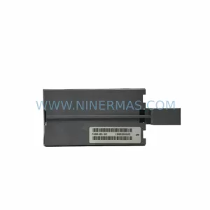
SKU: P0961BS-OD P0961BS-0D
Foxboro P0961BS-OD Safety-Reliable Bus Connector
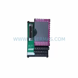
SKU: FBM203 P0916AE0C P0916AEOC
Foxboro FBM203 P0916AE0C Service-Ready Spare Part
Catalog Continuation
More FOXBORO modules in the catalog.
Use the brand lane to compare nearby part numbers, platform-adjacent modules, and other inquiry-ready listings before sending your final RFQ.
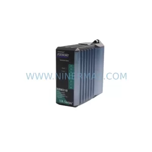
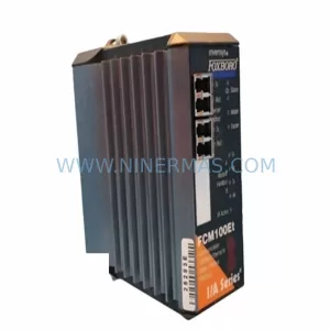
Catalog Continuation
Alternative parts within DCS Distributed Control Systems.
Stay inside the same system family when you need substitutes, adjacent modules, or a broader shortlist for procurement review.
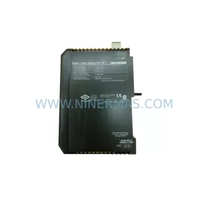
SKU: KJ1501X1-BB1 12P0678X042 VE5002
Emerson KJ1501X1-BB1 Retrofit Power Supply for Legacy DeltaV
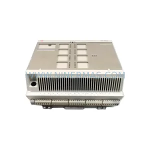
SKU: 8C-TCNT02 8U-TCNT02 8C-TCNTA1 8U-TCNTA1
Honeywell 8C-TCNT02 Service-Ready Spare Part for Industrial Maintenance