Original Industrial Spare Part
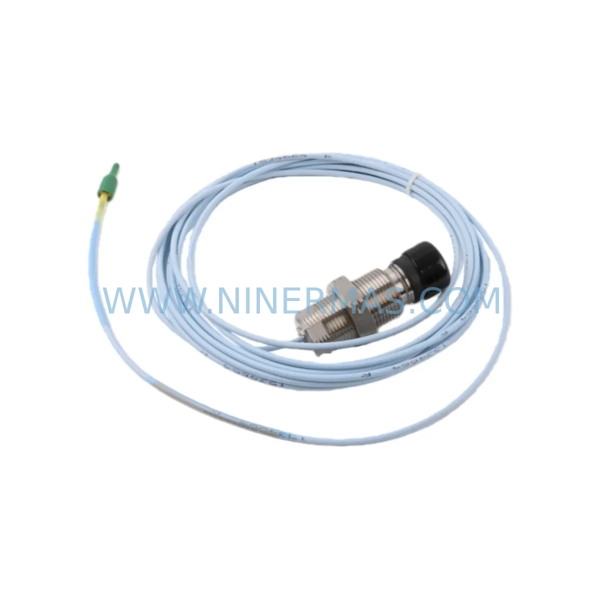
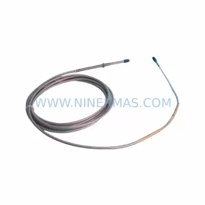
Bently Nevada 330851-02-000-060-50-00-CN Retrofit Proximity Probe
Verify the part, confirm the platform family, and move straight into quotation with the right commercial details.
RFQ Ready
- SKU330851-02-000-060-50-00-CN
- CategoryTSI & Rotating Machinery Monitoring
- BrandBently Nevada
- SupportAvailability, lead time, condition, and shipping coordination
How Buyers Usually Use This Page
- Confirm the exact part number and platform family before sending the quote request.
- Use direct email when quantity, condition, and destination are already defined internally.
- Switch to the broader brand or category archive when you need alternates nearby.
Series Navigation
Move through the most common platform families behind this part.
Product RFQ
Send this part directly for quotation.
Include quantity, required condition, destination country, and target delivery timing. Current reference: Bently Nevada 330851-02-000-060-50-00-CN Retrofit Proximity Probe with SKU 330851-02-000-060-50-00-CN.
Bently Nevada 330851-02-000-060-50-00-CN Retrofit-Compatible Proximity Probe for Legacy Vibration Monitoring Systems
The Bently Nevada 330851-02-000-060-50-00-CN is a ruggedized proximity probe module engineered for continuous vibration and position monitoring in rotating machinery applications. As a direct retrofit-compatible replacement for legacy Bently Nevada 3300 Series and 7200 Series proximity probe assemblies, this module supports smooth migration from end-of-life monitoring hardware without requiring full system overhauls. It is widely deployed in turbine control panels, compressor monitoring racks, and critical rotating equipment protection systems across oil & gas, power generation, and petrochemical industries.
When integrating the 330851-02-000-060-50-00-CN into an existing control cabinet, engineers must verify the probe tip diameter, cable length (the -060 suffix denotes a 60-inch extension cable), and the target material compatibility. The -50-00-CN suffix indicates a 5-meter system length with a standard 8 mm probe body, ruggedized for harsh environments. Confirm that the existing Proximitor® sensor — typically a 3300 XL 8mm Proximitor® Sensor or a 330180 series unit — is compatible with the probe’s sensitivity range (200 mV/mil) before installation.
Upgrade Compatibility Table
| Parameter | 330851-02-000-060-50-00-CN | Legacy 3300 Series Probes | Retrofit Notes |
|---|---|---|---|
| Probe Body Diameter | 8 mm | 8 mm | Direct mechanical fit; no bracket modification required |
| System Length | 5 m (196.9 in) | 5 m / 9 m options | Confirm extension cable length matches existing conduit routing |
| Sensitivity | 200 mV/mil (7.87 V/mm) | 200 mV/mil | Compatible with 3300 XL Proximitor® Sensor |
| Frequency Range | DC – 10,000 Hz | DC – 10,000 Hz | No signal conditioning changes required |
| Target Material | Steel / Stainless Steel | Steel / Stainless Steel | Verify shaft material; non-ferrous targets require recalibration |
| Connector Type | Standard BNC / Integral Cable | BNC | Check junction box terminal compatibility |
| Operating Temperature | -35°C to +121°C | -35°C to +121°C | Suitable for high-temperature turbine environments |
| Installation Space | Standard probe boss mount | Standard probe boss mount | No machining required for direct replacement |
| Communication / Signal | Analog voltage output | Analog voltage output | Compatible with 3500 Series rack monitors and legacy 3300 racks |
| Warranty | 12-Month Warranty — All units tested prior to shipment | ||
Retrofit Planning for Existing Automation Systems
Replacing a proximity probe assembly in a live rotating machinery protection system demands careful pre-engineering. Before removing the legacy probe, document the existing gap voltage reading (typically -10 VDC at the calibrated air gap) using the 3300 XL Proximitor® Sensor’s output terminals. This baseline reading is critical for post-installation verification and ensures the 330851-02-000-060-50-00-CN is correctly positioned within the linear range of the Proximitor® sensor.
In systems using a Bently Nevada 3500 Series Machinery Protection System rack, the probe signal feeds into a 3500/42M Proximitor®/Seismic Monitor or a 3500/40M Proximitor® Monitor card. Verify that the monitor card’s input configuration matches the probe sensitivity (200 mV/mil) and that the OK relay setpoints are adjusted if the new probe’s linear range differs slightly from the legacy unit. For older installations still running a 3300 Series rack, the 330851 probe is a direct drop-in replacement, but the rack’s power supply module — often a 3300/20 Power Supply — should be inspected for output stability before commissioning the new probe.
Cable routing is a frequent source of installation delays. The 330851-02-000-060-50-00-CN uses a 60-inch (approximately 1.5 m) extension cable between the probe and the Proximitor® sensor. Ensure the existing conduit or cable tray accommodates this length without sharp bends that could affect signal integrity. At the junction box, inspect the terminal block connections for corrosion and re-torque all terminals to specification. If the installation involves a 330130 or 330180 Proximitor® Sensor already mounted in the field, confirm the sensor’s power supply voltage (typically -24 VDC) is within tolerance before connecting the new probe.
For control systems that have migrated to a DCS or safety instrumented system (SIS) platform — such as a Honeywell Experion PKS, Emerson DeltaV, or ABB System 800xA — the analog output from the Proximitor® sensor feeds into an AI module on the DCS I/O rack. Verify the DCS input card’s signal range (0–10 VDC or 4–20 mA via a signal converter) and update the engineering unit scaling in the DCS configuration to reflect the new probe’s calibration. If a signal isolator or barrier (such as a Pepperl+Fuchs KFD2 series or MTL 5000 series Zener barrier) is installed in the signal loop for hazardous area compliance, confirm the barrier’s input/output characteristics are compatible with the 330851 probe’s output impedance.
In multi-channel monitoring applications — for example, a turbine with X-Y proximity probe pairs monitoring shaft radial vibration — replacing one probe while the machine is online requires careful coordination with the control room. The 3500 Series rack’s channel inhibit function should be activated for the affected channel to prevent spurious trips during the probe swap. After installation, perform a static gap check and a dynamic signal verification using a Bently Nevada ADRE 408 DSPi data acquisition system or equivalent portable analyzer to confirm the probe is operating within specification before releasing the channel inhibit.
Downtime Control During System Migration
Minimizing unplanned downtime during a proximity probe replacement is achievable with structured pre-work. Begin by staging all replacement components — including the 330851-02-000-060-50-00-CN probe, the extension cable, and any required junction box hardware — at least 48 hours before the planned maintenance window. Confirm that a spare 3300 XL Proximitor® Sensor is available on-site in case the existing sensor is found to be degraded during the probe swap.
Preserve the original program logic in the 3500 Series rack by exporting the rack configuration using Bently Nevada’s Rack Configuration Software (RCS) before any hardware changes. This configuration file captures all setpoint values, OK limits, transducer power settings, and communication parameters, allowing rapid restoration if the replacement introduces unexpected behavior. For systems integrated with a GE Mark VIe or Woodward MicroNet Plus turbine control system, ensure the vibration monitor’s Modbus or FOUNDATION Fieldbus communication link to the turbine controller is documented and tested post-replacement.
During the physical swap, use a non-conductive probe installation tool to avoid damaging the probe tip or the shaft surface. Set the air gap to the manufacturer’s specified value (typically 1.0 mm for an 8 mm probe) using a feeler gauge, then verify the gap voltage at the Proximitor® sensor output. A reading of approximately -10 VDC confirms correct installation. Re-enable the channel in the 3500 rack, observe the vibration trend for at least 15 minutes at operating speed, and confirm that the overall vibration level and 1X/2X components are consistent with pre-replacement baseline data. Document all as-found and as-left readings in the plant’s maintenance management system (CMMS) to support future reliability analysis and spare parts planning.
By following this structured approach, most proximity probe replacements can be completed within a 2–4 hour maintenance window, with machine restart and stabilization typically achieved within the same shift. All 330851-02-000-060-50-00-CN units supplied by NINERMAS are pre-tested and shipped with a test report, supporting rapid commissioning and reducing the risk of infant-failure returns.
Retrofit Support FAQ
Q1: Is the 330851-02-000-060-50-00-CN a direct replacement for my existing 3300 Series proximity probe?
A: Yes. The 330851-02-000-060-50-00-CN is mechanically and electrically compatible with the Bently Nevada 3300 Series and 3500 Series monitoring systems. It uses the same 8 mm probe body, 200 mV/mil sensitivity, and standard BNC/integral cable interface. No modifications to the Proximitor® sensor or monitor rack are required for a direct swap, provided the system length and extension cable length match your existing installation.
Q2: What commissioning steps are required after installation?
A: After mechanical installation, set the air gap to approximately 1.0 mm and verify the Proximitor® sensor output voltage (target: approximately -10 VDC). Re-enable the monitor channel in the 3500 rack, confirm OK relay status, and perform a dynamic signal check at operating speed. Update the as-left gap voltage in your CMMS and retain the factory test report supplied with the unit for traceability.
Q3: How do I confirm wiring compatibility with my existing junction box?
A: Compare the terminal designations on the existing probe’s extension cable connector with the 330851-02-000-060-50-00-CN wiring diagram. The probe uses a standard Bently Nevada color-coded cable (shield, center conductor) compatible with existing 3300 and 3500 Series junction boxes. If your installation uses a 330130 field-mount Proximitor® sensor, verify the sensor’s input connector type matches the probe’s cable termination.
Q4: What warranty and supply assurance does NINERMAS provide?
A: All 330851-02-000-060-50-00-CN units are covered by a 12-month warranty from the date of shipment. Each unit is tested prior to dispatch and shipped with a factory test report. NINERMAS maintains stock inventory to support urgent replacement requirements, with expedited shipping available for critical plant shutdowns. Contact sale@ninermas.com or +0086 187 5021 5667 for availability and lead time confirmation.
| Product Series | 3308 |
|---|---|
| Country of Origin | US |
Catalog Continuation
More Bently Nevada modules in the catalog.
Use the brand lane to compare nearby part numbers, platform-adjacent modules, and other inquiry-ready listings before sending your final RFQ.
SKU: 330851-06-000-070-10-00-CN
Bently Nevada 330851-06-000-070-10-00-CN Proximity Probe
SKU: 330905-00-18-50-02-00
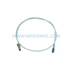
Bently Nevada 330905-00-18-50-02-00 Retrofit NSv Proximity Transducer
SKU: 330704-000-080-10-01-00
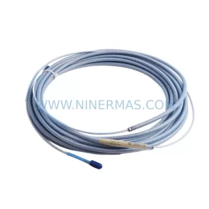
Bently Nevada 330704-000-080-10-01-00 Safety-Reliable Probe
Catalog Continuation
Alternative parts within TSI & Rotating Machinery Monitoring.
Stay inside the same system family when you need substitutes, adjacent modules, or a broader shortlist for procurement review.
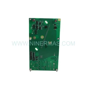
SKU: 21000-28-05-00-077-03-02
Bently Nevada 21000-28-05-00-077-03-02 Spare Part
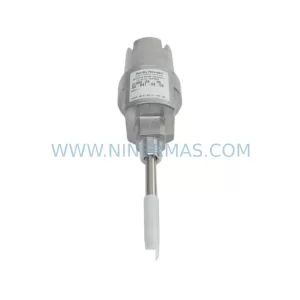
SKU: 330104-05-16-10-02-CN
Bently Nevada 330104-05-16-10-02-CN Retrofit-Compatible Proximity Transducer