Original Industrial Spare Part
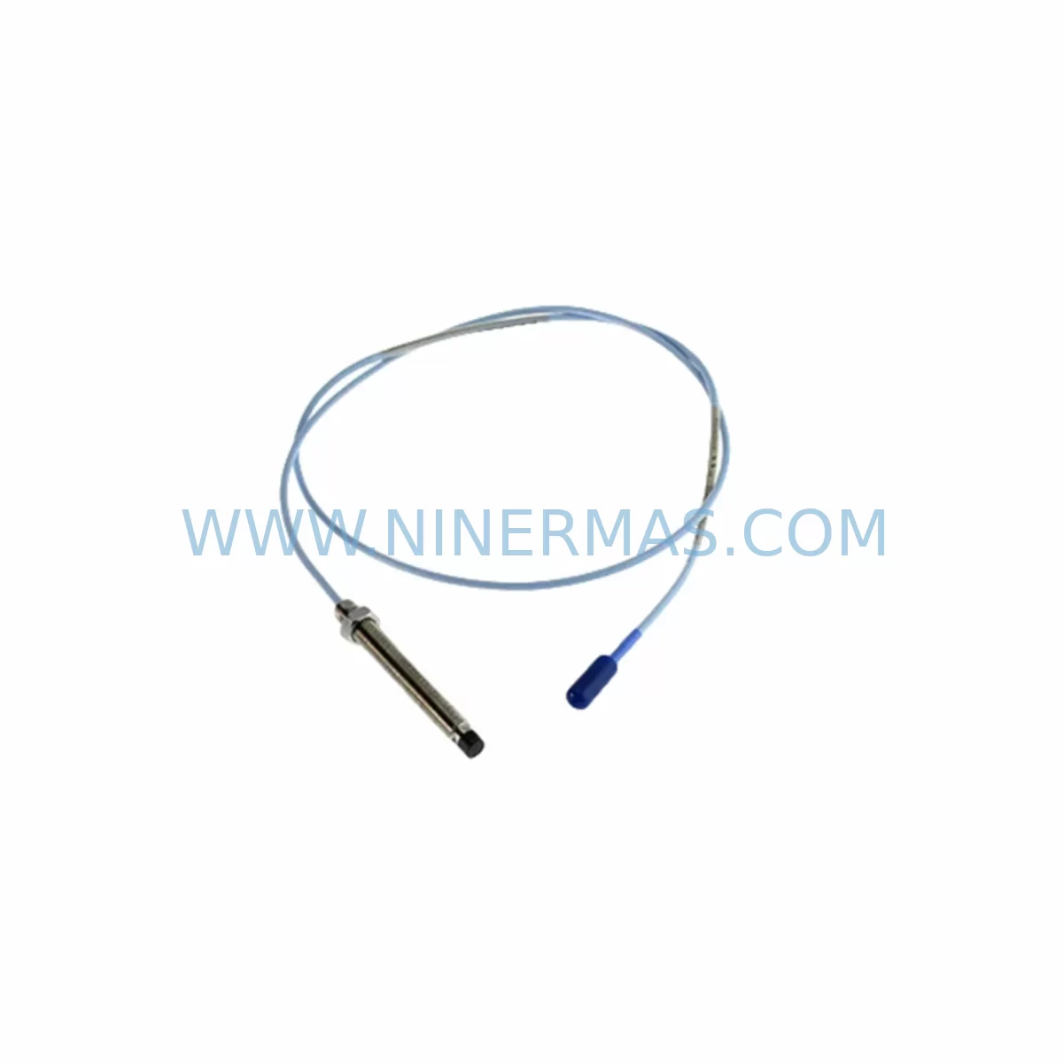
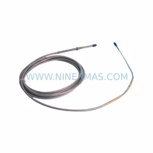
Bently Nevada 330130-045-12-00 Retrofit Extension Cable
Verify the part, confirm the platform family, and move straight into quotation with the right commercial details.
RFQ Ready
- SKU330130-045-12-00
- CategoryTSI & Rotating Machinery Monitoring
- BrandBently Nevada
- SupportAvailability, lead time, condition, and shipping coordination
How Buyers Usually Use This Page
- Confirm the exact part number and platform family before sending the quote request.
- Use direct email when quantity, condition, and destination are already defined internally.
- Switch to the broader brand or category archive when you need alternates nearby.
Series Navigation
Move through the most common platform families behind this part.
Product RFQ
Send this part directly for quotation.
Include quantity, required condition, destination country, and target delivery timing. Current reference: Bently Nevada 330130-045-12-00 Retrofit Extension Cable with SKU 330130-045-12-00.
Bently Nevada 330130-045-12-00 Retrofit Extension Cable: Legacy-Compatible Upgrade for 3500 Series Vibration Monitoring Systems
The Bently Nevada 330130-045-12-00 is a ruggedized extension cable module engineered for demanding industrial environments where signal integrity, mechanical durability, and long-term compatibility with legacy vibration monitoring infrastructure are non-negotiable. Designed as a direct retrofit solution for the Bently Nevada 3500 Series machinery protection system, this cable module bridges the gap between aging field installations and modern condition monitoring requirements — enabling plant engineers to extend the operational life of existing sensor networks without full system replacement.
In facilities running legacy Bently Nevada 7200 Series or 3300 Series proximity probes, the transition to a maintained 3500 Series rack often requires careful cable management. The 330130-045-12-00 provides the correct impedance matching, shielding characteristics, and connector geometry to interface directly with Proximitor® sensor assemblies, eliminating the need for custom field fabrication or signal conditioning workarounds. Its ruggedized jacket construction is rated for high-vibration, high-temperature, and chemically aggressive environments — making it suitable for turbine halls, compressor trains, pump skids, and rotating machinery platforms across oil and gas, power generation, and heavy manufacturing sectors.
Upgrade Compatibility Table
| Parameter | 330130-045-12-00 (This Unit) | Retrofit Notes |
|---|---|---|
| Compatible System | Bently Nevada 3500 Series | Also interfaces with 3300 Series Proximitor® assemblies in bridged configurations |
| Cable Length | 12.00 m (extension segment) | Verify total probe + extension does not exceed system-rated loop length |
| Connector Type | Standard Bently Nevada coaxial (BNC-compatible termination) | Confirm mating connector on existing Proximitor® or junction box before installation |
| Signal Compatibility | Eddy-current proximity signal (–24 VDC bias) | Do not mix with voltage-output or IEPE sensor cables |
| Installation Space | Flexible conduit routing; no rack slot required | Confirm conduit fill ratio and bend radius in existing cable trays |
| Communication Link | Analog signal passthrough (no protocol conversion required) | Downstream 3500/22M Transient Data Interface or 3500/42M Proximitor® I/O module must be verified for channel assignment |
| Replacement Path | Direct drop-in for 330130-045-xx-00 series variants | Cross-reference suffix for length variant; -12-00 = 12 m standard |
| Commissioning Requirement | Loop resistance check; gap voltage verification at Proximitor® | Target gap voltage: –10.0 VDC ±0.5 VDC at nominal air gap |
| Warranty | 12-Month Warranty — all units ship tested and certified | |
Retrofit Planning for Existing Automation Systems
Successful integration of the 330130-045-12-00 into a brownfield automation environment requires a structured pre-installation audit. Begin by documenting the existing probe-to-Proximitor® cable routing, noting junction box locations, conduit entry points, and any intermediate terminal blocks where signal splicing may have occurred over the system’s service life. In many legacy installations, the original Bently Nevada 330130-series cables have been spliced or extended informally — a practice that introduces impedance discontinuities and degrades the –24 VDC bias circuit, leading to false vibration alarms or gap voltage drift on the 3500/40M Proximitor® I/O module.
When planning the retrofit, engineers should simultaneously audit the 3500 Series rack configuration. Confirm that the 3500/15 Power Supply module is delivering stable ±24 VDC and ±5 VDC rails, as cable-related signal degradation is frequently misdiagnosed as power supply instability. If the rack includes a 3500/22M Transient Data Interface module for waveform capture, verify that the channel-to-slot mapping in the rack configuration software (System 1® or Rack Configuration Software) reflects the new cable routing before energizing the loop.
For installations where the 330130-045-12-00 is being used to extend reach to a remotely mounted Proximitor® sensor — common in large turbine pedestals or compressor skids with limited junction box access — confirm that the total cable loop length (probe cable + extension cable) remains within the Proximitor® model’s rated range. The 3300 XL 8mm Proximity Transducer System, for example, has a defined maximum loop resistance that must not be exceeded regardless of extension cable quality. Similarly, if the downstream monitoring rack includes a 3500/42M Proximitor® Monitor module, re-enter the probe scale factor and OK limit voltages in the module configuration to account for any loop resistance change introduced by the new extension segment.
In control cabinet upgrade projects where the 3500 Series rack is being relocated or a new 3500/05 Rack Interface Module is being commissioned, the 330130-045-12-00 provides the field-side continuity needed to maintain sensor connectivity during the transition. Pair this cable with a 3500/93 Display Interface Module or a dedicated HMI panel update to ensure that vibration trend data is correctly re-mapped after the rack move. If the facility uses a Modbus or OPC-DA communication link from the 3500 rack to a DCS or SCADA platform, verify that the rack’s communication module — typically a 3500/92 Communication Gateway Module — retains its tag assignments and polling configuration after the cable replacement is complete.
For I/O expansion projects where additional measurement points are being added to an existing 3500 rack, the 330130-045-12-00 is the correct field cable to pair with new 3500/40M or 3500/42M monitor modules. Ensure that the new channel’s Proximitor® sensor is of a compatible model — the 190501 or 330180 series Proximitor® assemblies are the most common retrofit-compatible options — and that the signal isolation requirements between adjacent channels are met to prevent cross-talk on high-channel-density racks.
Downtime Control During System Migration
Minimizing unplanned downtime during a cable retrofit on a live machinery protection system requires a disciplined bypass and hot-swap protocol. Before disconnecting the existing 330130-series cable, place the affected channel into bypass mode via the 3500 rack’s front-panel keyswitch or through the Rack Configuration Software, ensuring that the channel’s alarm outputs are inhibited and that the DCS or safety system receives a valid “channel bypassed” status signal rather than a spurious trip.
With the channel in bypass, disconnect the legacy cable at the junction box end first — not at the Proximitor® end — to preserve the sensor’s gap voltage and avoid disturbing the probe’s mechanical position in the bearing housing. Route the new 330130-045-12-00 through the existing conduit or cable tray, taking care to maintain the minimum bend radius specified for the cable’s ruggedized jacket. Reconnect at the junction box, then at the Proximitor® input, and perform a gap voltage measurement before removing the channel bypass. A reading of –10.0 VDC ±0.5 VDC confirms correct installation; readings outside this range indicate a wiring error, connector issue, or probe gap adjustment requirement.
For multi-channel retrofit campaigns — such as a full turbine train cable replacement covering radial vibration, axial position, and speed channels simultaneously — stage the work channel by channel rather than bypassing the entire rack at once. This approach preserves partial machinery protection coverage throughout the maintenance window and reduces the risk of a full protection system outage. Document each channel’s pre- and post-replacement gap voltage, OK relay status, and alarm setpoint verification in the site’s maintenance management system before returning the machine to service.
All 330130-045-12-00 units supplied by NINERMAS are pre-tested for continuity, insulation resistance, and shield integrity prior to shipment, reducing the risk of installation failures and supporting a faster return-to-service timeline. In-stock availability ensures that emergency cable replacements can be dispatched without the extended lead times associated with OEM direct procurement.
Retrofit Support FAQ
Q1: Is the 330130-045-12-00 a direct replacement for the original Bently Nevada cable, or does it require any field modification?
A: The 330130-045-12-00 is a direct drop-in replacement for the corresponding length variant in the 330130-045 series. No field modification, re-termination, or impedance matching adapter is required. Verify the suffix (-12-00 = 12 m) matches your existing installation before ordering.
Q2: What commissioning checks are required after installing the new extension cable?
A: Perform a gap voltage measurement at the Proximitor® output (target: –10.0 VDC ±0.5 VDC at nominal air gap), verify the OK relay is energized, confirm the channel’s vibration reading is within the expected baseline range, and remove the channel bypass in the 3500 rack configuration software. Log all readings in the site maintenance record.
Q3: Can this cable be used with non-Bently Nevada proximity probes or third-party Proximitor® equivalents?
A: The 330130-045-12-00 is optimized for use with Bently Nevada 3300 and 3500 Series Proximitor® sensor systems. Compatibility with third-party probes depends on the probe’s output impedance and bias voltage requirements. Consult your system integrator or contact NINERMAS technical support at sale@ninermas.com before using this cable with non-OEM sensor assemblies.
Q4: What warranty and supply terms apply to this unit?
A: All units carry a 12-month warranty covering manufacturing defects and electrical performance. NINERMAS maintains in-stock inventory for immediate dispatch, supporting both planned maintenance schedules and emergency replacement requirements. Contact sale@ninermas.com or +0086 187 5021 5667 for lead time confirmation and volume pricing.
| Product Series | 3500 series |
|---|---|
| Country of Origin | US |
Catalog Continuation
More Bently Nevada modules in the catalog.
Use the brand lane to compare nearby part numbers, platform-adjacent modules, and other inquiry-ready listings before sending your final RFQ.
SKU: 330704-000-080-10-01-00
Bently Nevada 330704-000-080-10-01-00 Safety-Reliable Probe
SKU: 21000-28-05-00-077-03-02
Bently Nevada 21000-28-05-00-077-03-02 Spare Part
SKU: 330104-05-16-10-02-CN
Bently Nevada 330104-05-16-10-02-CN Retrofit-Compatible Proximity Transducer
Catalog Continuation
Alternative parts within TSI & Rotating Machinery Monitoring.
Stay inside the same system family when you need substitutes, adjacent modules, or a broader shortlist for procurement review.
SKU: 1350-01083 852B61PCA2GC 0100-01692 0100-20458 P5/6X86 SBC, M9313-00126 960560-G4B
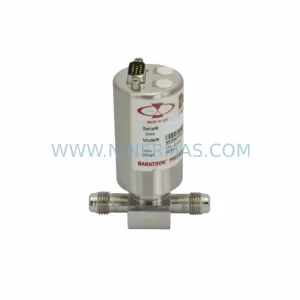
MKS 852B61PCA2GC Service-Ready Spare Part for Industrial Maintenance
SKU: 200-595-065-114/200-595-100-013
VIBRO METER 200-595-065-114 Service-Ready Spare Part