Original Industrial Spare Part
Bently Nevada 330104-10-19-10-02-00 Retrofit Proximity Transducer
Verify the part, confirm the platform family, and move straight into quotation with the right commercial details.

RFQ Ready
- SKU330104-10-19-10-02-00
- CategoryTSI & Rotating Machinery Monitoring
- BrandBently Nevada
- SupportAvailability, lead time, condition, and shipping coordination
How Buyers Usually Use This Page
- Confirm the exact part number and platform family before sending the quote request.
- Use direct email when quantity, condition, and destination are already defined internally.
- Switch to the broader brand or category archive when you need alternates nearby.
Series Navigation
Move through the most common platform families behind this part.
Product RFQ
Send this part directly for quotation.
Include quantity, required condition, destination country, and target delivery timing. Current reference: Bently Nevada 330104-10-19-10-02-00 Retrofit Proximity Transducer with SKU 330104-10-19-10-02-00.
Bently Nevada 330104-10-19-10-02-00 Retrofit Proximity Transducer: Legacy-Compatible Upgrade for 3300 XL Proximity Systems
The Bently Nevada 330104-10-19-10-02-00 is an eddy-current proximity transducer engineered for the 3300 XL Proximity System platform. Designed to measure radial shaft vibration, axial position, and differential expansion on rotating machinery, this transducer remains a critical spare for plants operating legacy turbine protection, compressor monitoring, and pump surveillance systems. As original production of this part has been discontinued, sourcing a verified retrofit-compatible replacement is essential for maintaining continuous machinery protection without triggering a full system overhaul.
At NINERMAS, we supply the 330104-10-19-10-02-00 from authenticated inventory channels, pre-tested against 3300 XL system specifications. Each unit ships with a 12-month warranty and full traceability documentation, supporting your maintenance team’s compliance and audit requirements.
Upgrade Compatibility Table
| Parameter | 330104-10-19-10-02-00 Specification | Retrofit Notes |
|---|---|---|
| Transducer Type | Eddy-Current Proximity (3-wire) | Compatible with 3300 XL driver/monitor pairs |
| Cable Length | 1.0 m integral cable | Verify extension cable length to reach driver; use 330130 extension if required |
| Thread Size | 10-32 UNF | Confirm existing bracket thread; re-tap if previously fitted with metric probe |
| Gap Voltage Range | −10 VDC to −18 VDC (nominal −14 VDC at 1.0 mm) | Re-gap to 1.0 mm after installation; verify with 3300 XL monitor channel |
| Driver Compatibility | 3300 XL 8 mm Driver (330180 series) | Do not mix with 5 mm or 14 mm driver families |
| Monitor Compatibility | 3300/16 Monitor, 3500/40M, 3500/42M | Confirm rack slot assignment and channel configuration in System 1 software |
| Installation Space | Standard 3300 XL probe boss | Check radial clearance; minimum 25 mm from adjacent metallic surfaces |
| Communication Link | Analog 4–20 mA / Keyphasor pulse | Verify Keyphasor 330180-90-00 signal continuity after replacement |
| Warranty | 12-Month Warranty — covers manufacturing defects and functional failure under normal operating conditions | |
Retrofit Planning for Existing Automation Systems
Replacing the 330104-10-19-10-02-00 in an active plant environment requires a structured approach that accounts for the full signal chain — from the probe tip through the extension cable, driver, and into the monitor rack. In most 3300 XL installations, the transducer is paired with a 330130-045-00-CN extension cable and a 330180-91-05 driver mounted in a field junction box. Before removing the old probe, technicians should record the existing gap voltage reading from the 3300/16 Monitor or 3500/40M channel display to establish a baseline for post-installation verification.
In control cabinets where the 3300 XL rack is integrated alongside a 3500/20 Rack Interface Module and a 3500/92 Communication Gateway, the replacement sequence must preserve the Modbus or Ethernet/IP communication link to the DCS or SCADA layer. Any interruption to the gateway’s polling cycle can trigger spurious alarms in the historian or cause the System 1 Evolution condition monitoring software to log a false channel fault. Coordinate with the control room operator to suppress the affected channel alarm before pulling the probe.
For plants that have already partially migrated to the Bently Nevada 3500 Series platform, the 330104-10-19-10-02-00 can coexist in a hybrid rack configuration where legacy 3300 XL monitors occupy lower slots and newer 3500/40M Proximitor Monitor cards occupy upper slots. In this scenario, confirm that the rack’s 3500/15 Power Supply provides sufficient current headroom — each 3300 XL channel draws approximately 25 mA from the −24 VDC bus, and adding a replacement probe without auditing total rack current can cause intermittent power brownouts affecting adjacent I/O modules.
Terminal wiring at the field junction box should be inspected during the replacement. The three-conductor shielded cable (shield, center conductor, outer conductor) must be landed on the correct terminals of the 330180 driver; reversed polarity will produce a positive gap voltage that the monitor interprets as a probe fault. Use a calibrated gap-setting tool or a precision feeler gauge to set the probe face-to-shaft gap to 1.0 mm (±0.05 mm) before tightening the locknut. After mechanical installation, confirm the gap voltage reads between −10 VDC and −18 VDC on the driver’s test point.
Where the original installation used a Keyphasor 330180-90-00 transducer for phase reference, verify that the Keyphasor signal is still present on the monitor’s Keyphasor input after the proximity probe replacement. Loss of Keyphasor signal will disable 1X and 2X vibration vector calculations in System 1, masking early-warning imbalance trends. If the Keyphasor probe is also approaching end-of-life, consider replacing it concurrently to avoid a second planned outage. Similarly, if the plant uses a 3300 XL Velomitor seismic sensor on the same machine train, inspect its connector and cable integrity during the same maintenance window to consolidate downtime.
For sites planning a longer-term migration to the Bently Nevada 3701/40 Machinery Protection System or the Orbit 60 Series, the 330104-10-19-10-02-00 serves as a bridge spare that maintains protection continuity while the migration project is scoped and budgeted. NINERMAS maintains buffer stock of this part specifically to support multi-year retrofit programs where procurement lead times for new-platform hardware can extend to 16–24 weeks.
Downtime Control During System Migration
Minimizing unplanned downtime during a proximity probe replacement begins with pre-staging. Before the maintenance window opens, verify that the replacement 330104-10-19-10-02-00 has been bench-tested: connect it to a spare 330180 driver, apply −24 VDC, and confirm the gap voltage curve matches the published sensitivity of −7.87 V/mm. A unit that fails bench verification before installation avoids the scenario of discovering a defective spare after the machine is already offline.
During the replacement, protect the original PLC or DCS program logic by placing the affected monitor channel in bypass mode rather than allowing it to trip the machine on a probe fault signal. Most 3500/40M and 3300/16 monitors support a software bypass via the System 1 interface or a front-panel keyswitch. Document the bypass activation time in the maintenance log to satisfy safety management system requirements.
After the new probe is installed and gapped, perform a slow-roll check at shaft speeds below 600 RPM to confirm the gap voltage is stable and the vibration reading is within the expected noise floor (typically below 2 µm pk-pk at slow roll). Only after this verification should the bypass be removed and the channel returned to normal protection mode. This sequence ensures that the machine is never simultaneously unprotected and at operating speed.
For plants with redundant measurement paths — for example, where both X and Y radial probes are installed on the same bearing — the Y-axis probe can remain active while the X-axis probe is replaced, maintaining at least partial vibration protection throughout the procedure. This approach is consistent with IEC 61511 partial stroke testing philosophy and reduces the risk window to the duration of the physical swap rather than the entire maintenance window.
NINERMAS supports expedited shipping for emergency replacement scenarios, with same-day dispatch available for in-stock units. All units are shipped with individual test certificates, gap sensitivity data, and installation torque specifications to support rapid field commissioning without requiring the maintenance team to source supplementary documentation.
Retrofit Support FAQ
Q1: Is the 330104-10-19-10-02-00 a direct drop-in replacement for earlier 330104 variants?
The 330104-10-19-10-02-00 is part of the 330104 family of 8 mm eddy-current proximity transducers. The suffix digits encode cable length, connector type, and temperature rating. Before ordering, confirm that the cable length (1.0 m integral), connector style (2-pin MIL-C-5015), and operating temperature range match your installation requirements. If your existing installation uses a different suffix variant, contact our technical team to confirm interchangeability within your specific driver and monitor combination.
Q2: What commissioning steps are required after installation?
After mechanical installation and gap setting, perform the following: (1) verify gap voltage at the driver test point (−10 to −18 VDC); (2) confirm channel status in the 3300/16 or 3500/40M monitor (no fault LED); (3) check System 1 historian for a clean signal trace at slow roll; (4) remove channel bypass and confirm alarm setpoints are active. Document all readings in the maintenance record before returning the machine to service.
Q3: Does NINERMAS perform pre-shipment functional testing?
Yes. Every 330104-10-19-10-02-00 unit supplied by NINERMAS undergoes pre-shipment functional testing including gap voltage linearity verification across the full measurement range. A test certificate is included with each shipment. Units that do not meet Bently Nevada published specifications are quarantined and not dispatched. This process supports your incoming inspection requirements and reduces commissioning risk.
Q4: What is covered under the 12-month warranty?
The 12-month warranty covers manufacturing defects, functional failure under normal operating conditions, and out-of-specification gap sensitivity at time of installation. It does not cover damage resulting from incorrect installation, reversed polarity wiring, mechanical impact, or operation outside the specified temperature and vibration envelope. Warranty claims are processed with return of the defective unit and the original test certificate. Replacement units are dispatched within 5 business days of claim approval.
| Product Series | 3301 |
|---|---|
| Country of Origin | US |
Catalog Continuation
More Bently Nevada modules in the catalog.
Use the brand lane to compare nearby part numbers, platform-adjacent modules, and other inquiry-ready listings before sending your final RFQ.
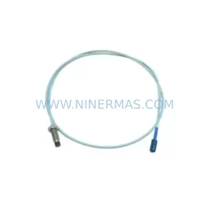
SKU: 330704-000-080-10-01-00
Bently Nevada 330704-000-080-10-01-00 Safety-Reliable Probe
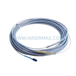
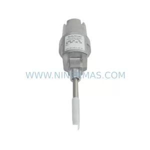
SKU: 21000-28-05-00-077-03-02
Bently Nevada 21000-28-05-00-077-03-02 Spare Part
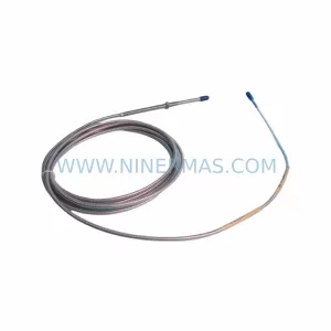
SKU: 330104-05-16-10-02-CN
Bently Nevada 330104-05-16-10-02-CN Retrofit-Compatible Proximity Transducer
Catalog Continuation
Alternative parts within TSI & Rotating Machinery Monitoring.
Stay inside the same system family when you need substitutes, adjacent modules, or a broader shortlist for procurement review.
SKU: 1350-01083 852B61PCA2GC 0100-01692 0100-20458 P5/6X86 SBC, M9313-00126 960560-G4B
MKS 852B61PCA2GC Service-Ready Spare Part for Industrial Maintenance
SKU: 200-595-065-114/200-595-100-013
VIBRO METER 200-595-065-114 Service-Ready Spare Part