Original Industrial Spare Part
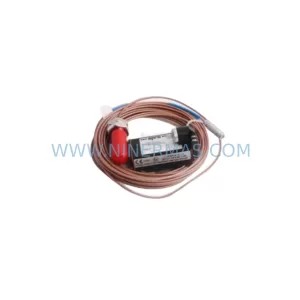
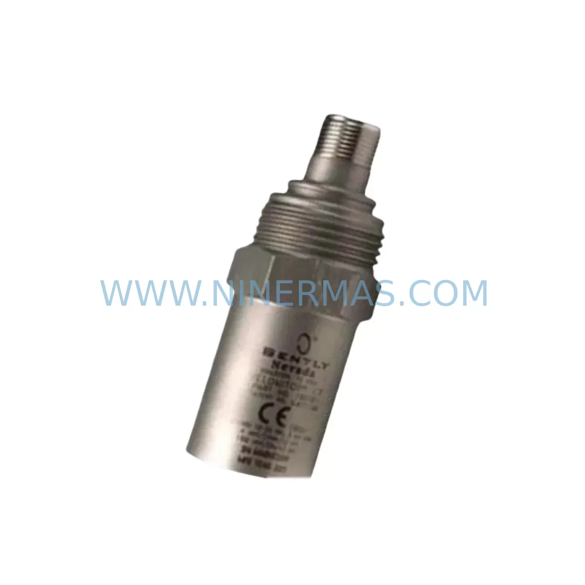
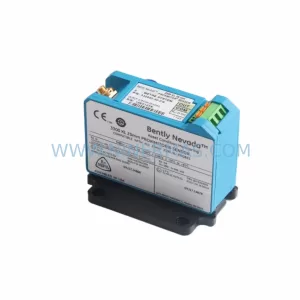
Bently Nevada 190501-16-00-00 Retrofit-Compatible Velomitor CT Sensor
Verify the part, confirm the platform family, and move straight into quotation with the right commercial details.
RFQ Ready
- SKU190501-16-00-00
- CategoryTSI & Rotating Machinery Monitoring
- BrandBently Nevada
- SupportAvailability, lead time, condition, and shipping coordination
How Buyers Usually Use This Page
- Confirm the exact part number and platform family before sending the quote request.
- Use direct email when quantity, condition, and destination are already defined internally.
- Switch to the broader brand or category archive when you need alternates nearby.
Series Navigation
Move through the most common platform families behind this part.
Product RFQ
Send this part directly for quotation.
Include quantity, required condition, destination country, and target delivery timing. Current reference: Bently Nevada 190501-16-00-00 Retrofit-Compatible Velomitor CT Sensor with SKU 190501-16-00-00.
Bently Nevada 190501-16-00-00 Retrofit-Compatible Velomitor CT Sensor: Legacy System Compatibility & Smooth Upgrade Path
The Bently Nevada 190501-16-00-00 is a Velomitor CT Series piezo-velocity vibration sensor engineered for continuous machinery protection in rotating equipment applications. As legacy Bently Nevada monitoring platforms age and original spare parts reach end-of-life, the 190501-16-00-00 remains one of the most sought-after retrofit-compatible components for engineers tasked with modernizing existing control cabinets without full system replacement. Whether you are sustaining an aging turbine protection loop, replacing a failed sensor on a compressor train, or migrating from an older 7200 Series rack to a current 3500 Series monitoring system, this sensor provides the electrical and mechanical compatibility required for a controlled, low-risk upgrade.
Upgrade Compatibility Table
| Parameter | Details |
|---|---|
| SKU / Part Number | 190501-16-00-00 |
| Series | Velomitor CT (Piezo-Velocity) |
| Output Signal | Velocity (mV/mm/s or mV/in/s), compatible with 3500/42M and 3500/42E monitor modules |
| Connector / Interface | 2-pin MIL-C-5015 style connector; verify mating connector on existing field wiring harness before installation |
| Installation Requirement | Radial or axial mounting; confirm thread size and mounting pad dimensions against legacy sensor footprint |
| Communication Compatibility | Analog signal; compatible with 3500 rack Keyphasor and I/O modules; no protocol conversion required |
| Replacement Recommendation | Direct replacement for discontinued Velomitor CT variants; confirm cable length suffix matches field run |
| Commissioning Focus | Verify bias voltage, sensitivity scaling in monitor, and alarm setpoints after swap |
| Warranty | 12-Month Warranty from date of shipment |
Retrofit Planning for Existing Automation Systems
Successful integration of the 190501-16-00-00 into an existing machinery protection system begins well before the sensor arrives on site. Engineers working on legacy plant retrofits typically encounter a mix of Bently Nevada 3500 Series rack components — including the 3500/20 rack interface module, 3500/42M machinery protection monitor, 3500/15 power supply module, and 3500/22M transient data interface — all of which must be confirmed operational before a sensor swap is treated as the root cause of a monitoring fault.
In many brownfield installations, the 190501-16-00-00 is mounted alongside older Proximitor 3300 XL proximity probes and extension cables that feed into the same 3500 rack. When planning the retrofit, technicians should document the existing terminal block wiring at the junction box, confirm the barrier or isolator model in the signal path (such as a Bently Nevada 3500/33 16-channel relay module or an external Zener barrier), and verify that the new sensor’s sensitivity specification — typically 100 mV/g — matches the scaling configured in the monitor’s software database.
For sites migrating from the older 7200 Series monitoring platform to the current 3500 architecture, the 190501-16-00-00 sensor itself is often the most straightforward element of the upgrade. The greater complexity lies in re-engineering the I/O wiring from the field junction boxes back to the new rack, reconfiguring the System 1 condition monitoring software to recognize the updated channel assignments, and ensuring that the Keyphasor signal — often sourced from a 330180 proximity probe — is correctly routed to the new rack’s Keyphasor module. During this phase, a programming cable such as the 3500/93 communication gateway or a direct Ethernet connection to the rack’s TCP/IP port is required to push the updated configuration.
Where the control cabinet includes a Bently Nevada 3500/61 temperature monitor or a 3500/40M proximitor monitor in adjacent slots, technicians must confirm that the rack backplane addressing is updated to reflect the new sensor channel map. Failure to update the rack configuration database before energizing the new sensor is one of the most common causes of false alerts during commissioning. It is strongly recommended to perform a bench-level output simulation — injecting a known velocity signal into the monitor input — before the machine is returned to service.
Downtime Control During System Migration
Minimizing unplanned downtime during a sensor replacement or monitoring system upgrade requires a structured pre-outage preparation process. For the 190501-16-00-00, the following approach has proven effective across compressor, turbine, and pump train applications:
First, capture a full export of the existing 3500 rack configuration using System 1 or the Rack Configuration Software (RCS) before any hardware is disturbed. This preserves all alarm setpoints, transducer scale factors, and channel enable states, and provides a rollback baseline if commissioning reveals unexpected behavior. Second, photograph or sketch the existing terminal wiring at both the sensor connector and the rack I/O terminal strip, noting wire colors, shield termination points, and any jumper settings on the I/O module.
During the physical swap, keep the machine in a controlled coast-down or locked-out state and avoid leaving the monitor channel in a bypassed condition for longer than necessary. Once the 190501-16-00-00 is installed and the connector is secured, power the sensor and verify the bias voltage at the monitor input — a reading within the sensor’s specified bias range confirms the sensor is correctly wired and not internally damaged. Only after bias voltage is confirmed should the channel bypass be removed and the alarm system returned to active monitoring.
For sites where continuous operation is critical, a temporary portable vibration analyzer can be used to shadow-monitor the machine during the transition window, providing an independent reference that allows the protection system to be briefly taken offline without losing visibility of machine health. This approach is particularly valuable when the 190501-16-00-00 is being installed as part of a broader upgrade that also involves replacing the 3500/42M monitor module or reconfiguring the System 1 data server.
Retrofit Support FAQ
Q1: Is the 190501-16-00-00 a direct drop-in replacement for my existing Velomitor CT sensor?
In most cases, yes — provided the cable length suffix and connector type match your existing installation. The 190501-16-00-00 shares the same piezo-velocity operating principle and output sensitivity as other Velomitor CT variants. Before ordering, confirm the full part number suffix against your existing sensor label or engineering drawing to ensure the cable length and termination style are compatible with your field run and junction box layout.
Q2: Has this unit been tested before shipment?
Yes. All units supplied by NINERMAS undergo pre-shipment functional verification, including bias voltage output check and sensitivity confirmation where test equipment permits. Each unit ships with a 12-month warranty from the date of shipment, covering manufacturing defects and functional failures under normal operating conditions.
Q3: What should I check during commissioning after installing the 190501-16-00-00?
After physical installation, verify the bias voltage at the monitor input terminal (typically between -7 VDC and -11 VDC for a healthy Velomitor CT sensor). Confirm that the sensitivity scaling in the 3500/42M or equivalent monitor module matches the sensor’s rated output. Check that alarm setpoints have not been inadvertently reset during any rack configuration update. Finally, perform a bump test or use a portable calibrator to confirm the monitor is responding correctly to a known vibration input before returning the machine to service.
Q4: Do you maintain stock of the 190501-16-00-00 and related Bently Nevada components?
Yes. NINERMAS maintains inventory of the 190501-16-00-00 and a range of associated Bently Nevada 3500 Series components to support urgent retrofit and breakdown replacement requirements. Lead times for in-stock units are typically short, and expedited shipping is available for critical plant situations. Contact our team to confirm current availability and discuss your project timeline.
| Product Series | 3500 series |
|---|---|
| Country of Origin | US |
Catalog Continuation
More Bently Nevada modules in the catalog.
Use the brand lane to compare nearby part numbers, platform-adjacent modules, and other inquiry-ready listings before sending your final RFQ.
SKU: 330194-13-20-10-00
Bently Nevada 330194-13-20-10-00 Safety-Reliable Monitor for Critical Control
SKU: 330701-00-40-10-11-05
Bently Nevada 330701-00-40-10-11-05 Safety Vibration Monitor
SKU: 21000-33-05-00-035-03-02
Bently Nevada 21000-33-05-00-035-03-02 Safety Relay
Catalog Continuation
Alternative parts within TSI & Rotating Machinery Monitoring.
Stay inside the same system family when you need substitutes, adjacent modules, or a broader shortlist for procurement review.