Original Industrial Spare Part
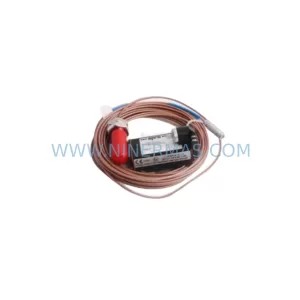
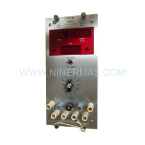
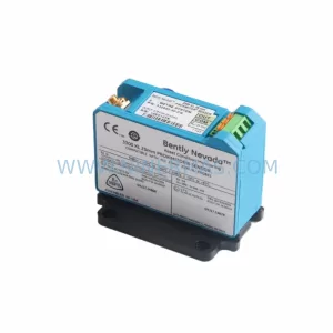
Bently Nevada 190501-09-00-04 Retrofit Velomitor CT Transmitter
Verify the part, confirm the platform family, and move straight into quotation with the right commercial details.
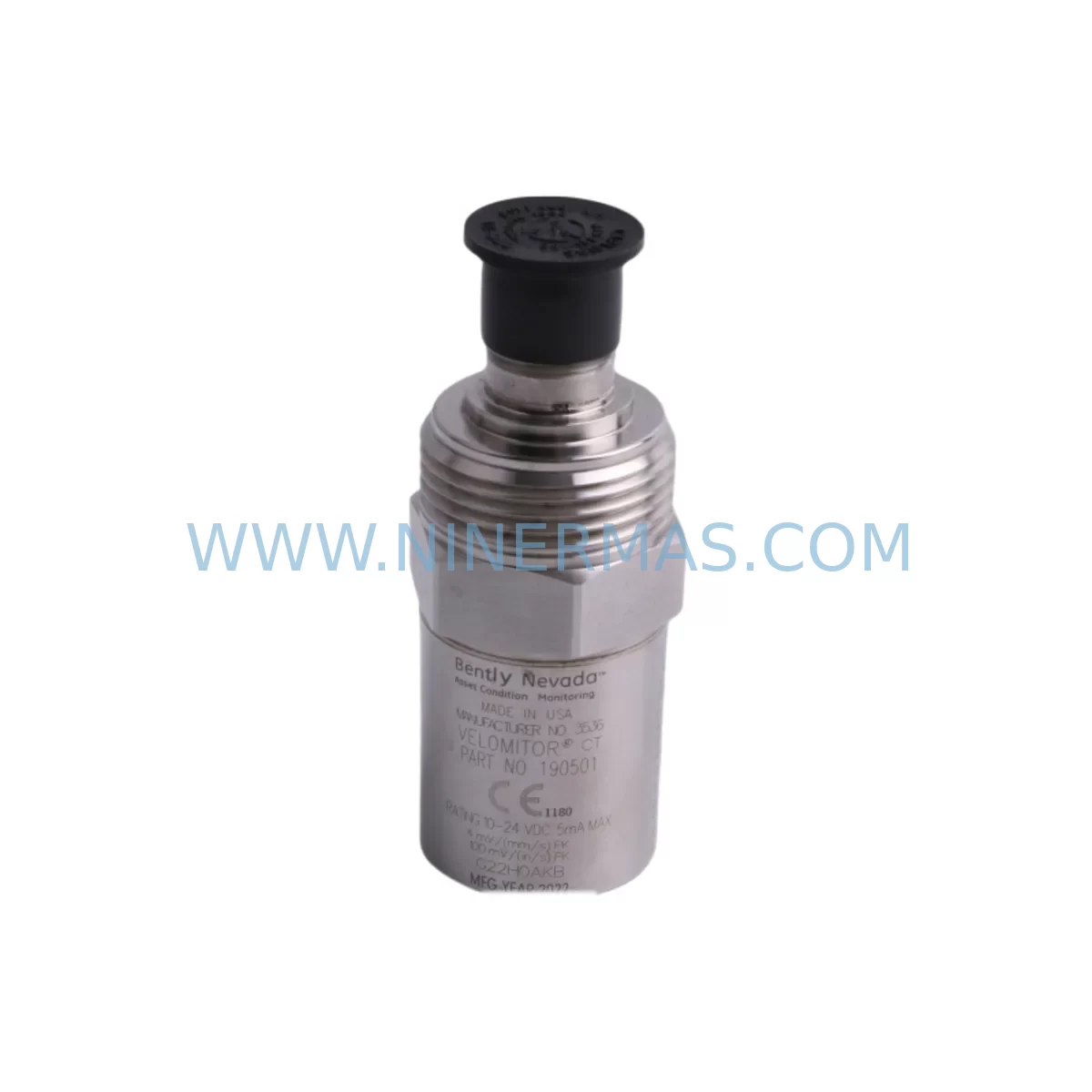
RFQ Ready
- SKU190501-09-00-04
- CategoryTSI & Rotating Machinery Monitoring
- BrandBently Nevada
- SupportAvailability, lead time, condition, and shipping coordination
How Buyers Usually Use This Page
- Confirm the exact part number and platform family before sending the quote request.
- Use direct email when quantity, condition, and destination are already defined internally.
- Switch to the broader brand or category archive when you need alternates nearby.
Series Navigation
Move through the most common platform families behind this part.
Product RFQ
Send this part directly for quotation.
Include quantity, required condition, destination country, and target delivery timing. Current reference: Bently Nevada 190501-09-00-04 Retrofit Velomitor CT Transmitter with SKU 190501-09-00-04.
Bently Nevada 190501-09-00-04 Retrofit Velomitor CT Transmitter: Legacy System Compatibility and Smooth Upgrade Path
The Bently Nevada 190501-09-00-04 is a Velomitor CT Series piezo-velocity transmitter engineered for continuous vibration monitoring on rotating machinery. Designed to deliver a 4–20 mA output signal proportional to casing velocity, this transmitter integrates directly with Bently Nevada 3500 Series rack-based monitoring systems and legacy 7200 Series proximity systems. As original equipment reaches end-of-life and spare parts become increasingly scarce, the 190501-09-00-04 serves as a critical retrofit-compatible replacement that allows facilities to extend the operational life of existing control architectures without committing to a full platform migration.
For maintenance engineers managing aging turbine trains, compressor skids, or pump monitoring panels, sourcing a verified replacement for the 190501-09-00-04 is often the difference between a planned outage and an unscheduled shutdown. NINERMAS maintains in-stock inventory of this transmitter, pre-shipment tested and supplied with a 12-month warranty, ensuring that your retrofit project proceeds on schedule with documented quality assurance.
Upgrade Compatibility Table
| Parameter | 190501-09-00-04 Specification | Retrofit / Replacement Notes |
|---|---|---|
| Output Signal | 4–20 mA (velocity proportional) | Compatible with 3500/42M and 3500/45 monitor modules; verify input card scaling |
| Frequency Range | 2–1000 Hz (typical Velomitor CT range) | Confirm process frequency band matches existing alarm setpoints in 3500 rack |
| Mounting Interface | 1/4-28 UNF threaded stud or adhesive pad | Verify existing mounting boss thread; adapter studs available for metric M6 surfaces |
| Cable / Connector | Integral cable, MIL-C-5015 or flying leads | Match connector type to existing junction box or field wiring; re-termination may be required |
| Power Supply | 18–30 VDC loop-powered | Confirm 3500 rack I/O power rail voltage; no separate excitation supply required |
| Communication Protocol | Analog 4–20 mA (HART optional on select variants) | If migrating to digital, pair with 3500/22M transient data interface for Modbus/TCP bridge |
| Installation Space | Compact body, ~Ø25 mm × 50 mm | Fits standard bearing housing pads; confirm clearance on gearbox or motor end-bell |
| Replacement Compatibility | Direct replacement for 190501-09-00-01 / -02 / -03 variants | Verify suffix digit for cable length and connector type before ordering |
| Commissioning Requirement | Zero-point calibration via 3500 rack software (System 1 or Rack Configuration) | Re-enter transducer sensitivity (mV/mm/s) in monitor module after swap |
| Warranty | 12-Month Warranty — All units pre-shipment tested; documentation available on request | |
Retrofit Planning for Existing Automation Systems
Replacing the 190501-09-00-04 in an operating plant requires a structured approach that accounts for the full signal chain — from the sensor mounting point through the field junction box, into the 3500 Series rack, and ultimately to the DCS or historian. Before removing the existing transmitter, maintenance teams should document the current 4–20 mA loop resistance, verify the terminal block wiring diagram at the local junction box, and confirm the transducer sensitivity value stored in the associated Bently Nevada 3500/42M Proximitor/Seismic Monitor module. Failure to re-enter the correct sensitivity after replacement will cause the rack to report incorrect velocity readings and may trigger nuisance alarms or mask real machinery faults.
In many legacy installations, the 190501-09-00-04 is wired back to a Bently Nevada 3500/20 Rack Interface Module that handles system power distribution and communication with the plant DCS via a 3500/92 Communication Gateway using Modbus RTU or Ethernet/IP. If the retrofit scope includes upgrading this communication path — for example, migrating from serial Modbus to Modbus/TCP — the gateway module configuration must be updated in parallel with the sensor swap to avoid a loss of monitoring data at the DCS historian.
For facilities running mixed monitoring architectures, the 190501-09-00-04 may coexist in the same control cabinet with Bently Nevada 3300 XL 8mm Proximity Transducer Systems monitoring shaft displacement on the same machine train. In this case, the retrofit plan must address both the velocity channel (Velomitor CT) and the proximity channels simultaneously if the rack is being reconfigured, since module slot assignments and I/O addresses are interdependent within the 3500 rack backplane.
Where the existing installation uses a Bently Nevada TK-3 Termination Block or a 3500/15 Power Supply that is also approaching end-of-life, it is operationally efficient to replace these components during the same planned outage window. Combining the sensor swap with a power supply replacement eliminates a second outage event and reduces total lifecycle risk. Similarly, if the plant historian is connected via a System 1 Evolution software platform, the asset database should be updated to reflect the new transmitter serial number and calibration date immediately after commissioning.
For installations where the Velomitor CT feeds into a standalone Bently Nevada 1900/65A General Purpose Equipment Monitor rather than a full 3500 rack, the retrofit procedure is simpler: the 1900/65A accepts the same 4–20 mA input, and only the alarm setpoints and full-scale range need to be verified after the sensor is replaced. This makes the 190501-09-00-04 a versatile spare that supports both rack-based and standalone monitoring architectures across a wide range of rotating equipment applications.
In facilities where space inside the control cabinet is constrained, engineers should also verify that the replacement transmitter cable routing does not create interference with adjacent Bently Nevada 3500/40M Proximitor Monitor signal cables. Crosstalk between velocity and proximity signal cables can introduce noise into the monitoring system, particularly in high-vibration environments near large motors or gearboxes. Proper cable segregation and grounding at the junction box are essential steps in the commissioning checklist.
Downtime Control During System Migration
Minimizing downtime during a Velomitor CT replacement begins with pre-staging. Before the planned outage, the replacement 190501-09-00-04 should be bench-tested against a known signal source to verify output linearity across the 4–20 mA range. The transducer sensitivity value (typically expressed in mV/mm/s or mV/in/s) should be recorded from the existing unit’s nameplate or the 3500 rack configuration file and pre-loaded into the replacement module configuration offline using Bently Nevada’s Rack Configuration Software.
During the outage window, the recommended sequence is: (1) isolate the loop at the field junction box and tag out the terminal block; (2) remove the existing transmitter and document the as-found mounting condition and cable routing; (3) install the replacement 190501-09-00-04 using the same mounting stud and torque specification; (4) re-terminate the field cable at the junction box, verifying polarity; (5) restore loop power and confirm the 4–20 mA output at the rack input card using a calibrated loop calibrator; (6) verify alarm and danger setpoints in the 3500 monitor module are unchanged; (7) release the machine for restart.
This sequence, when executed by a trained instrumentation technician, typically requires 2–4 hours per measurement point, allowing a single-shift outage to cover multiple sensor replacements on the same machine train. Pre-shipment testing by NINERMAS ensures that the replacement unit arrives ready for installation, eliminating the risk of discovering a defective spare during the outage window — a scenario that can extend downtime by days when replacement parts must be expedited from overseas.
For critical machinery where continuous monitoring is contractually required, a temporary portable vibration monitor can be deployed on the machine during the sensor swap to maintain surveillance and satisfy insurance or regulatory requirements. Once the replacement 190501-09-00-04 is commissioned and the 3500 rack confirms a valid 4–20 mA signal, the portable monitor can be removed and the machine returned to normal supervised operation.
Retrofit Support FAQ
Q1: Is the 190501-09-00-04 a direct drop-in replacement for earlier Velomitor CT variants such as the 190501-09-00-01 or -02?
A: In most cases, yes — the core electrical interface (4–20 mA, loop-powered, 18–30 VDC) is consistent across the Velomitor CT family. However, the suffix digits indicate differences in cable length, connector type, and temperature rating. Always verify the suffix against your existing installation drawing before ordering to ensure the replacement matches the field wiring and environmental requirements.
Q2: What commissioning steps are required after installing the replacement transmitter in a 3500 rack system?
A: After physical installation and loop re-termination, you must verify the transducer sensitivity value in the 3500/42M or 3500/45 monitor module using Rack Configuration Software. Confirm that the full-scale range, alarm setpoints, and danger setpoints are unchanged. Perform a loop calibration check using a 4–20 mA source to verify end-to-end signal integrity before releasing the machine for operation.
Q3: Can the 190501-09-00-04 be used with non-Bently Nevada monitoring systems?
A: Yes. Because the output is a standard 4–20 mA analog signal, the 190501-09-00-04 is compatible with any monitoring system or DCS input card that accepts a 4–20 mA loop-powered transmitter. Scaling and engineering unit conversion must be configured at the receiving system based on the transmitter’s published sensitivity specification.
Q4: What warranty and quality assurance documentation is provided with each unit?
A: Every 190501-09-00-04 supplied by NINERMAS is covered by a 12-month warranty from the date of shipment. Each unit undergoes pre-shipment functional testing, and a test report is available upon request. Units are shipped in anti-static packaging with original or equivalent labeling. Long-term supply programs and blanket order arrangements are available for facilities requiring ongoing spare parts coverage for lifecycle extension programs.
| Product Series | 3500 series |
|---|---|
| Country of Origin | US |
Catalog Continuation
More Bently Nevada modules in the catalog.
Use the brand lane to compare nearby part numbers, platform-adjacent modules, and other inquiry-ready listings before sending your final RFQ.
SKU: 330194-13-20-10-00
Bently Nevada 330194-13-20-10-00 Safety-Reliable Monitor for Critical Control
SKU: 330701-00-40-10-11-05
Bently Nevada 330701-00-40-10-11-05 Safety Vibration Monitor
SKU: 21000-33-05-00-035-03-02
Bently Nevada 21000-33-05-00-035-03-02 Safety Relay
Catalog Continuation
Alternative parts within TSI & Rotating Machinery Monitoring.
Stay inside the same system family when you need substitutes, adjacent modules, or a broader shortlist for procurement review.