Original Industrial Spare Part
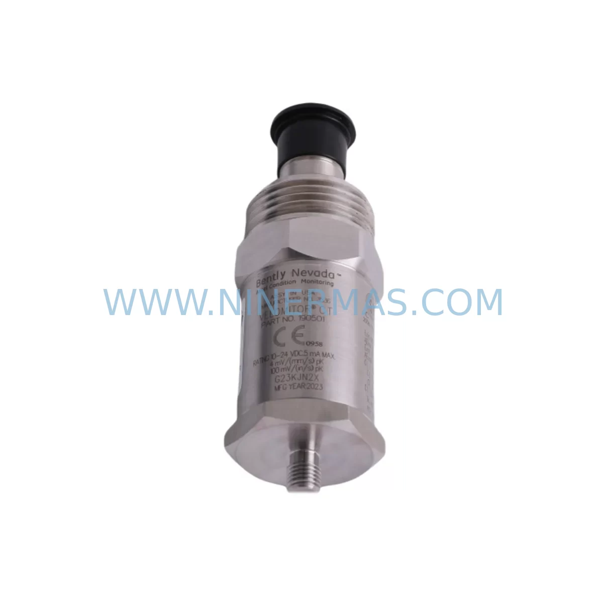
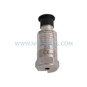
Bently Nevada 190501-05-99-01 Retrofit Velocity Transducer
Verify the part, confirm the platform family, and move straight into quotation with the right commercial details.
RFQ Ready
- SKU190501-05-99-01
- CategoryTSI & Rotating Machinery Monitoring
- BrandBently Nevada
- SupportAvailability, lead time, condition, and shipping coordination
How Buyers Usually Use This Page
- Confirm the exact part number and platform family before sending the quote request.
- Use direct email when quantity, condition, and destination are already defined internally.
- Switch to the broader brand or category archive when you need alternates nearby.
Series Navigation
Move through the most common platform families behind this part.
Product RFQ
Send this part directly for quotation.
Include quantity, required condition, destination country, and target delivery timing. Current reference: Bently Nevada 190501-05-99-01 Retrofit Velocity Transducer with SKU 190501-05-99-01.
Bently Nevada 190501-05-99-01 Retrofit Velocity Transducer: Legacy System Compatible Upgrade
The Bently Nevada 190501-05-99-01 is a ruggedized velocity transducer engineered for continuous vibration monitoring in demanding industrial environments. As legacy rotating machinery protection systems reach end-of-life, this unit serves as a direct retrofit-compatible replacement for discontinued velocity sensors across a wide range of turbine, compressor, pump, and motor monitoring applications. Whether you are upgrading an aging Bently Nevada 3300 Series rack, migrating from a 7200 Series monitoring platform, or restoring a decommissioned machinery protection system, the 190501-05-99-01 provides a reliable, field-proven solution that minimizes engineering rework and reduces total downtime during the changeover.
Upgrade Compatibility Table
| Parameter | 190501-05-99-01 Specification | Retrofit Notes |
|---|---|---|
| Sensor Type | Velocity Transducer (Seismic) | Direct replacement for legacy seismic velocity probes |
| Output Signal | Voltage (mV/mm/s or mV/in/s) | Verify monitor input card signal range before swap |
| Connector / Termination | 2-pin MIL-spec connector | Check existing cable pinout; adapter may be required for older wiring harnesses |
| Mounting Interface | Threaded stud mount | Confirm thread size matches existing bearing housing boss |
| Operating Temperature | -40°C to +121°C | Suitable for high-temperature turbine bearing pedestals |
| Communication Compatibility | Analog signal to 3300/7200 monitor cards | Compatible with Bently Nevada 3300/16 and 3500/42 velocity monitor modules |
| Installation Space | Standard probe body diameter | Confirm clearance in existing conduit and junction box |
| Replacement Recommendation | 1:1 drop-in for 190501 series variants | Cross-reference suffix codes (-05, -99, -01) for sensitivity and cable length |
| Commissioning Focus | Zero-speed baseline, full-speed vibration trend | Log pre-swap baseline; compare post-installation trend data |
| Warranty | 12-Month Warranty | Covered from date of shipment; includes functional test certificate |
Retrofit Planning for Existing Automation Systems
Successful integration of the Bently Nevada 190501-05-99-01 into an existing machinery protection architecture requires a structured pre-engineering review. Begin by auditing the current monitor rack configuration. In most legacy installations, the velocity transducer feeds directly into a Bently Nevada 3300/16 Velocity Monitor or a 3500/42M Velocity/Acceleration Monitor module seated in a 3500 Rack. Confirm that the existing monitor card’s input impedance and sensitivity range are compatible with the 190501-05-99-01 output characteristics before proceeding with physical removal of the old sensor.
Terminal wiring is a critical checkpoint. The 190501-05-99-01 uses a shielded two-conductor cable terminated at the field junction box. When replacing an older 190501 variant, inspect the existing shielded cable for insulation degradation, especially in high-temperature zones near turbine casings. If the cable run exceeds the recommended length for the monitor card’s input circuit, signal attenuation may affect vibration amplitude accuracy. In such cases, a signal conditioner or barrier isolator should be inserted between the transducer and the 3500 rack input terminal block.
For installations where the 190501-05-99-01 is being introduced into a modernized control architecture — for example, a migration from a standalone Bently Nevada rack to an integrated Emerson Ovation DCS or a Rockwell Automation ControlLogix PLC-based monitoring loop — the analog output of the transducer must be routed through an appropriate analog input module. Confirm the AI module’s input range (typically 0–10 V or ±5 V) matches the transducer’s output at maximum rated velocity. If the existing HMI screens in the Wonderware InTouch or FactoryTalk View SE environment display vibration trend data, update the engineering unit scaling in the tag database to reflect the new transducer’s sensitivity coefficient.
Backplane and rack space verification is equally important. If the 3500 Rack is being partially upgraded alongside the transducer swap — for instance, adding a 3500/22M Transient Data Interface or a 3500/92 Communication Gateway module — confirm that the rack has sufficient slot capacity and that the power supply module (such as the 3500/15 Power Supply) can support the additional load. Overloading the rack power budget is a common oversight during phased upgrades and can cause intermittent monitor resets that are difficult to diagnose in the field.
Where the retrofit involves migrating from a legacy Keyphasor-based phase reference system, verify that the 3500/25 Enhanced Keyphasor Module is present and correctly configured in the rack. The 190501-05-99-01 velocity data is most meaningful when correlated with shaft phase reference signals for spectrum analysis and balancing diagnostics. If the Keyphasor probe — typically a 330180 or 330130 proximity probe — has also reached end-of-life, plan its replacement concurrently to avoid a second outage window.
Programming compatibility should be reviewed if the vibration data feeds into a safety instrumented system or a PLC-based interlock. Confirm that the existing function block or ladder logic rung referencing the velocity channel tag does not require recalibration after the transducer swap. In most cases, if the replacement unit’s sensitivity matches the original, no program changes are needed. However, if the suffix codes differ (indicating a different sensitivity range), update the scaling constants in the PLC program and re-validate the high-vibration trip setpoint against the machinery OEM’s alarm and trip recommendations.
Downtime Control During System Migration
Minimizing unplanned downtime is the primary operational concern when replacing a velocity transducer on a running production asset. The recommended approach is to schedule the swap during a planned maintenance window — ideally coinciding with a scheduled oil change, coupling inspection, or bearing replacement — so that the machine is already offline and the additional time required for transducer removal, installation, and commissioning does not extend the total outage duration.
Before the machine is shut down, capture a full vibration baseline using the existing transducer. Export the trend data and spectrum plots from the Bently Nevada System 1 software or equivalent condition monitoring platform. This baseline serves as the acceptance reference for post-installation commissioning. After installing the 190501-05-99-01, perform a static continuity check on the cable and connector before energizing the monitor rack. Power up the 3500 rack and verify that the monitor card displays a valid, noise-free signal at zero speed. Slowly bring the machine to operating speed while monitoring the vibration trend in real time. Compare the live amplitude and frequency spectrum against the pre-swap baseline. If the overall vibration level is within ±10% of the baseline at the same operating speed and load, the installation is considered successful.
To further protect the original control logic during the migration, do not modify any PLC program or DCS configuration until the transducer has been confirmed operational. If the vibration channel feeds a safety relay or a trip logic block, temporarily bypass the trip output (with appropriate management of change authorization) during the commissioning phase to prevent a spurious machine trip caused by transient signal noise during cable reconnection. Restore the trip logic immediately after the commissioning check is complete and documented.
For sites where a cold standby spare is maintained, the 190501-05-99-01 can be pre-tested on a bench using a calibrated vibration shaker table before it is brought to the field. This pre-shipment functional test, combined with the 12-month warranty coverage from the date of shipment, ensures that the replacement unit is confirmed operational before the machine is taken offline, eliminating the risk of discovering a defective spare during a live outage.
Retrofit Support FAQ
Q1: Is the Bently Nevada 190501-05-99-01 a direct drop-in replacement for other 190501 suffix variants?
A: In most cases, yes — provided the suffix codes indicate the same sensitivity range and cable length. The -05 suffix typically denotes a specific sensitivity (e.g., 100 mV/in/s), while -99 and -01 relate to cable configuration and connector type. Always cross-reference the original datasheet or the System 1 configuration file to confirm the sensitivity coefficient before installation. If the sensitivity differs, update the scaling in the monitor card or PLC tag accordingly.
Q2: What wiring checks are required before connecting the 190501-05-99-01 to an existing 3500 rack?
A: Verify cable shield continuity, insulation resistance (minimum 100 MΩ at 500 VDC), and correct polarity at the terminal block. Confirm that the shield is grounded at one end only (typically at the monitor rack end) to prevent ground loop interference. Check the terminal block label on the 3500/42M or 3300/16 monitor card for the correct channel assignment before tightening the termination screws.
Q3: How is compatibility with the existing HMI and SCADA system verified after the transducer swap?
A: After installation, navigate to the vibration trend display in the Wonderware, FactoryTalk, or Ignition SCADA screen and confirm that the engineering unit value (mm/s or in/s RMS) matches the expected reading at the current operating speed. If the displayed value is significantly higher or lower than the pre-swap baseline, check the sensitivity scaling constant in the monitor card configuration or the PLC analog input scaling block. No HMI screen redesign should be required if the replacement unit’s output range matches the original.
Q4: What does the 12-month warranty cover, and is a functional test certificate included?
A: The 12-month warranty covers manufacturing defects and functional failures under normal operating conditions from the date of shipment. Each unit is shipped with a functional test certificate confirming that the transducer output was verified against a calibrated reference before dispatch. In-stock units are available for immediate shipment, supporting urgent replacement scenarios where minimizing machine downtime is critical. For warranty claims or technical support, contact sale@ninermas.com or call +0086 187 5021 5667.
| Product Series | 3500 series |
|---|---|
| Country of Origin | US |
Catalog Continuation
More Bently Nevada modules in the catalog.
Use the brand lane to compare nearby part numbers, platform-adjacent modules, and other inquiry-ready listings before sending your final RFQ.
SKU: 330880-16-15-020-01-02
Bently Nevada 330880-16-15-020-01-02 Service-Ready Spare Part
SKU: 330910-00-13-10-02-05
Bently Nevada 330910-00-13-10-02-05 Safety-Reliable Proximity Transducer
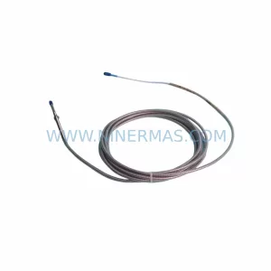
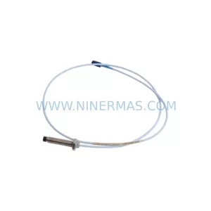
SKU: 330103-00-10-10-11-05
Bently Nevada 330103-00-10-10-11-05 Safety Proximity Transducer
Catalog Continuation
Alternative parts within TSI & Rotating Machinery Monitoring.
Stay inside the same system family when you need substitutes, adjacent modules, or a broader shortlist for procurement review.
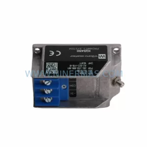
SKU: 204-900-000-011
Vibro-meter 204-900-000-011 Safety-Reliable Vibration Monitor
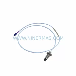
SKU: 330703-000-060-90-02-00
Bently Nevada 330703-000-060-90-02-00 Retrofit Module
SKU: 177230-00-01-CN 16925-33
Bently Nevada 177230-00-01-CN 16925-33 Service-Ready Spare Part for Industrial Maintenance