Original Industrial Spare Part
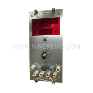
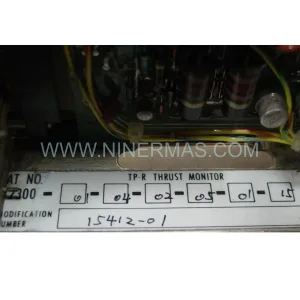
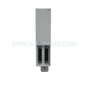
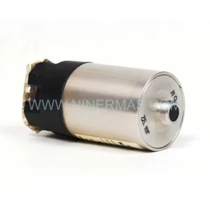
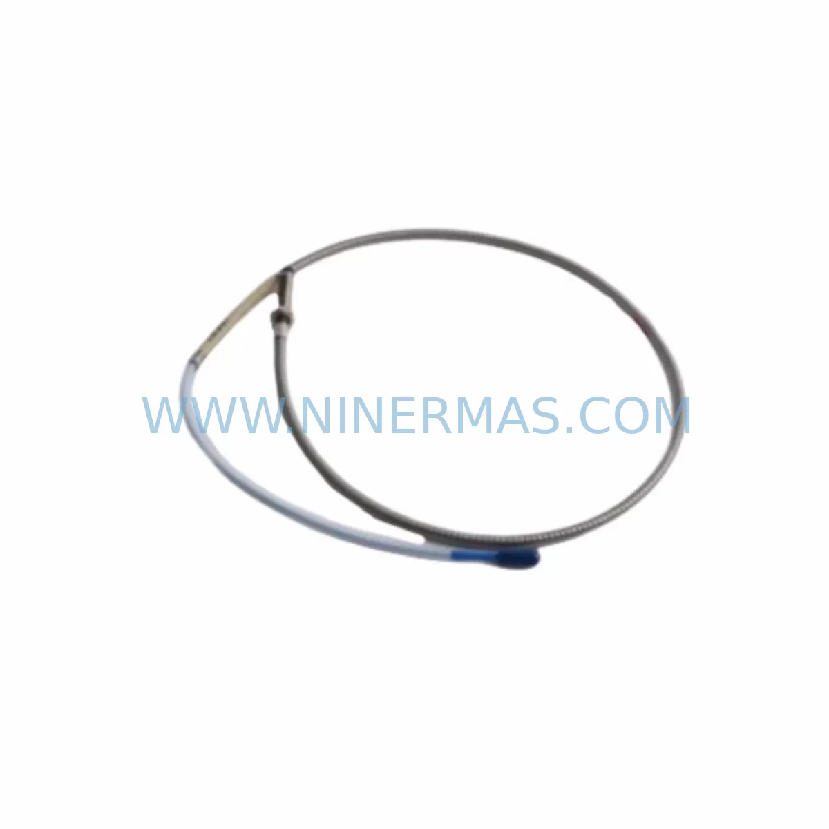
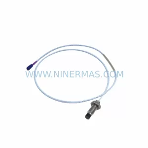
Bently Nevada 102244-22-50-01 Retrofit-Compatible Vibration Transmitter
Verify the part, confirm the platform family, and move straight into quotation with the right commercial details.
RFQ Ready
- SKU102244-22-50-01
- CategoryTSI & Rotating Machinery Monitoring
- BrandBently Nevada
- SupportAvailability, lead time, condition, and shipping coordination
How Buyers Usually Use This Page
- Confirm the exact part number and platform family before sending the quote request.
- Use direct email when quantity, condition, and destination are already defined internally.
- Switch to the broader brand or category archive when you need alternates nearby.
Series Navigation
Move through the most common platform families behind this part.
Product RFQ
Send this part directly for quotation.
Include quantity, required condition, destination country, and target delivery timing. Current reference: Bently Nevada 102244-22-50-01 Retrofit-Compatible Vibration Transmitter with SKU 102244-22-50-01.
Bently Nevada 102244-22-50-01 Retrofit-Compatible Vibration Transmitter for Legacy System Modernization
The Bently Nevada 102244-22-50-01 is a high-reliability vibration transmitter engineered for seamless integration into existing machinery protection and condition monitoring systems. As legacy Bently Nevada platforms approach end-of-life and original spare parts become increasingly scarce, the 102244-22-50-01 serves as a proven retrofit solution for facilities seeking to extend the operational life of their rotating equipment monitoring infrastructure without committing to a full system overhaul. Whether you are managing a turbine protection panel, a compressor monitoring rack, or a general-purpose vibration monitoring cabinet, this transmitter delivers the signal conditioning and output compatibility required to maintain continuous protection with minimal disruption to existing wiring and programming.
Engineers undertaking a retrofit or spare-part replacement project with the 102244-22-50-01 should begin by confirming the power supply capacity of the existing control cabinet. The transmitter operates within standard Bently Nevada voltage rails, but aging power supply modules — particularly those shared across multiple I/O channels — may require load recalculation before adding or swapping transmitter modules. Verifying terminal block wiring against the original loop drawing is equally critical: field wiring polarity, shielding continuity, and cable routing must be preserved to avoid introducing ground loops or signal noise that can trigger false alarms or mask genuine machinery faults.
Backplane interface compatibility is another key checkpoint. In rack-based Bently Nevada installations, the 102244-22-50-01 must be confirmed against the specific rack slot assignments and module addressing scheme used in the original configuration. Systems built around the 3300 Series rack architecture, for example, use a defined slot-to-channel mapping that must be maintained when substituting modules. If the replacement is being installed into a rack that previously housed a different transmitter variant, the module address settings — typically configured via DIP switches or internal jumpers — must be matched to the original channel assignment to ensure the monitoring system correctly identifies and processes the vibration signal.
Program compatibility verification is essential before returning the system to service. Control logic in the associated safety or condition monitoring system — whether hosted on a dedicated machinery protection system or integrated into a broader DCS or PLC platform — references specific channel tags, alarm setpoints, and trip thresholds tied to the original transmitter’s output range. Confirming that the 102244-22-50-01 output signal (typically 4–20 mA or voltage proportional to vibration amplitude) matches the input expectations of the receiving controller prevents the need for setpoint recalibration and reduces commissioning time significantly.
HMI screen updates are often overlooked during transmitter replacements. If the facility uses a SCADA or HMI platform displaying real-time vibration trends, alarm banners, or historical data from the replaced channel, the engineering team should verify that tag names, engineering unit scaling, and display ranges remain consistent after the swap. In many legacy installations, HMI configurations are not version-controlled, making pre-retrofit screen captures a valuable reference during post-installation verification.
Communication link integrity should also be confirmed where the vibration data is transmitted over a serial or fieldbus network — such as Modbus RTU, FOUNDATION Fieldbus, or a proprietary Bently Nevada communication protocol — to a plant historian or asset management system. The 102244-22-50-01 retrofit should not alter the data frame structure or polling address visible to the upstream system, but this must be validated during the commissioning phase rather than assumed.
Upgrade Compatibility Table
| Parameter | Details |
|---|---|
| SKU / Part Number | 102244-22-50-01 |
| Brand / Series | Bently Nevada / 3300 Series Compatible |
| Function | Vibration Transmitter — Signal Conditioning & Output |
| Output Signal | 4–20 mA / Voltage (application-dependent) |
| Installation Interface | Rack-mount, backplane slot compatible |
| Communication Compatibility | Modbus RTU, proprietary Bently Nevada protocol |
| Replacement Suitability | Direct retrofit for discontinued / EOL transmitter variants |
| Terminal Wiring | Verify against original loop drawing before installation |
| Commissioning Requirement | Module address, DIP switch, and setpoint verification required |
| Warranty | 12 Months from date of shipment |
Retrofit Planning for Existing Automation Systems
A successful retrofit using the 102244-22-50-01 typically involves coordinating several interdependent system components. In a typical machinery protection cabinet, the transmitter interfaces with a Bently Nevada 3300/16 Power Supply or equivalent rack power module, which must be confirmed as capable of supporting the additional load introduced by the replacement unit. The rack itself — often a Bently Nevada 3300/05 or 3300/10 chassis — must have an available slot with the correct backplane pinout for the transmitter module.
Field sensors connected to the transmitter, such as Bently Nevada 330100 or 330130 Series proximity probes and extension cables, must be inspected for continuity and insulation resistance before the new transmitter is energized. A degraded probe or cable can produce erratic output that is easily misattributed to the replacement transmitter, leading to unnecessary troubleshooting delays. Similarly, the Bently Nevada 3300 XL 8mm or 11mm proximitor/sensor assemblies used as the primary sensing element should be verified for gap voltage within the manufacturer’s specified range.
Where the vibration monitoring system feeds into a broader control architecture — for example, a Honeywell DCS, an ABB 800xA system, or a Rockwell Automation ControlLogix platform — the analog input card receiving the 4–20 mA signal from the 102244-22-50-01 must be confirmed for input range and scaling. In some installations, a signal isolator or signal conditioner is installed between the transmitter output and the DCS analog input to provide galvanic isolation and protect against ground potential differences between the field and control room. These isolator modules should be tested for correct pass-through scaling after the transmitter replacement.
For facilities managing multiple protection channels simultaneously, the retrofit plan should sequence the replacement of individual transmitter modules to maintain at least partial system coverage at all times. Replacing all channels simultaneously in a multi-channel rack risks leaving rotating equipment unprotected during the commissioning window, which is unacceptable in most process safety frameworks. A phased approach — replacing and verifying one channel before proceeding to the next — is strongly recommended.
Downtime Control During System Migration
Minimizing unplanned downtime during a transmitter retrofit requires a structured pre-outage preparation process. Before the maintenance window opens, the engineering team should complete a full documentation review: loop drawings, rack layout diagrams, module address tables, alarm setpoint records, and HMI tag lists should all be assembled and cross-checked against the as-built system configuration. Any discrepancies between documentation and the actual installed configuration should be resolved before the outage begins, not during it.
The original program logic — whether residing in a Bently Nevada System 1 software platform, a dedicated safety system, or an integrated DCS — should be backed up immediately before any hardware is disturbed. This backup serves as both a recovery reference and a commissioning baseline. If the replacement transmitter requires any setpoint adjustment or scaling change, the original values provide the starting point for the new configuration.
During the physical swap, maintaining field wiring continuity is the single most effective way to reduce commissioning time. Where possible, the existing terminal block connections should be transferred to the new module without re-routing cables, preserving the original wiring topology and minimizing the risk of miswiring. After installation, a cold-start verification sequence — energizing the transmitter, confirming output signal levels at the rack output terminals, and verifying alarm and trip thresholds at the monitoring system — should be completed before the equipment is returned to service.
Post-retrofit, a 24–48 hour monitoring period with enhanced alarm surveillance is recommended to confirm stable operation under normal process conditions. Any drift in the vibration signal baseline relative to pre-retrofit historical trends should be investigated before the enhanced monitoring period is concluded. NINERMAS provides full pre-shipment functional testing on all 102244-22-50-01 units, with test records available upon request, to reduce the risk of field failures during this critical commissioning window.
Retrofit Support FAQ
Q: Is the 102244-22-50-01 a direct drop-in replacement for the original Bently Nevada part?
A: The 102244-22-50-01 is designed for retrofit compatibility with legacy Bently Nevada rack-based systems. Physical dimensions, backplane interface, and output signal characteristics are matched to the original specification. However, module address settings (DIP switches or jumpers) must be verified and configured to match the original channel assignment before installation.
Q: What pre-shipment testing is performed on each unit?
A: Every 102244-22-50-01 unit shipped by NINERMAS undergoes functional output verification, insulation resistance testing, and visual inspection prior to dispatch. Test records are available upon request. All units are covered by a 12-month warranty from the date of shipment.
Q: How do I confirm wiring compatibility with my existing terminal blocks?
A: Reference your original loop drawing for terminal assignments, wire gauge, and shielding requirements. The 102244-22-50-01 uses standard Bently Nevada terminal conventions. If your loop drawing is unavailable, NINERMAS technical support can assist with terminal identification based on the rack model and slot position.
Q: What is the lead time and stock availability?
A: NINERMAS maintains inventory of the 102244-22-50-01 to support urgent retrofit and breakdown replacement requirements. Standard lead time for in-stock units is 3–7 business days for international shipments. Contact our team for current stock status and expedited shipping options.
| Product Series | 3300 |
|---|---|
| Country of Origin | US |
Catalog Continuation
More Bently Nevada modules in the catalog.
Use the brand lane to compare nearby part numbers, platform-adjacent modules, and other inquiry-ready listings before sending your final RFQ.
SKU: 21000-28-10-00-167-04-02
Bently Nevada 21000-28-10-00-167-04-02 Retrofit Proximity Probe
SKU: 330880-16-15-020-01-02
Bently Nevada 330880-16-15-020-01-02 Service-Ready Spare Part
SKU: 330910-00-13-10-02-05
Bently Nevada 330910-00-13-10-02-05 Safety-Reliable Proximity Transducer
Catalog Continuation
Alternative parts within TSI & Rotating Machinery Monitoring.
Stay inside the same system family when you need substitutes, adjacent modules, or a broader shortlist for procurement review.
SKU: 330103-00-10-10-11-05
Bently Nevada 330103-00-10-10-11-05 Safety Proximity Transducer
SKU: 204-900-000-011
Vibro-meter 204-900-000-011 Safety-Reliable Vibration Monitor
SKU: 330703-000-060-90-02-00
Bently Nevada 330703-000-060-90-02-00 Retrofit Module