Original Industrial Spare Part
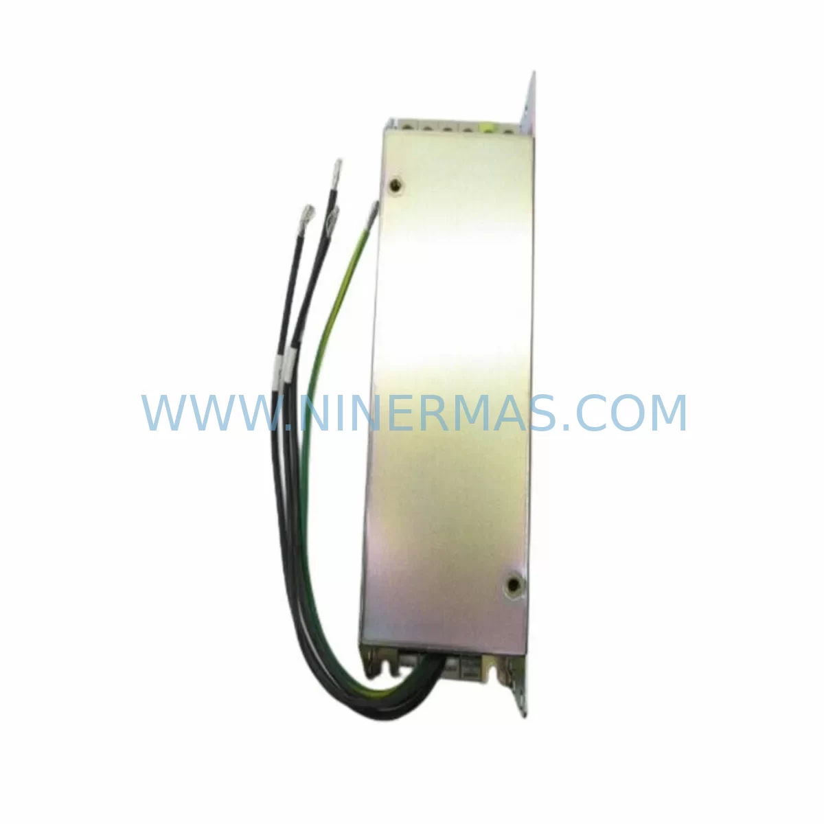
Allen-Bradley 25-RF7P5-AL Retrofit EMC Filter for Legacy Drives
Verify the part, confirm the platform family, and move straight into quotation with the right commercial details.
RFQ Ready
- SKU25-RF7P5-AL
- CategoryPLC & Industrial Automation Modules
- BrandAllen-Bradley
- SupportAvailability, lead time, condition, and shipping coordination
How Buyers Usually Use This Page
- Confirm the exact part number and platform family before sending the quote request.
- Use direct email when quantity, condition, and destination are already defined internally.
- Switch to the broader brand or category archive when you need alternates nearby.
Series Navigation
Move through the most common platform families behind this part.
Product RFQ
Send this part directly for quotation.
Include quantity, required condition, destination country, and target delivery timing. Current reference: Allen-Bradley 25-RF7P5-AL Retrofit EMC Filter for Legacy Drives with SKU 25-RF7P5-AL.
Allen-Bradley 25-RF7P5-AL Retrofit EMC Filter for Legacy Drive Systems
The Allen-Bradley 25-RF7P5-AL is a retrofit-compatible EMC/RFI line filter designed for the PowerFlex 525 AC drive platform, rated for 7.5HP (5.5kW) applications. As legacy automation systems age and original spare parts become increasingly difficult to source, the 25-RF7P5-AL provides a verified drop-in solution for facilities managing aging variable frequency drive (VFD) installations across process control, HVAC, conveyor, and pump applications.
This filter suppresses conducted electromagnetic interference on the AC input line, ensuring compliance with EN 61800-3 Category C2/C3 EMC standards when integrated with PowerFlex 525 drives. For plants running legacy PowerFlex 4 or PowerFlex 40 drive cabinets that are being migrated to the PowerFlex 525 platform, the 25-RF7P5-AL is a critical component in maintaining EMC compliance without redesigning the control cabinet layout.
Upgrade Compatibility Table
| Parameter | Details |
|---|---|
| Part Number | 25-RF7P5-AL |
| Compatible Drive | PowerFlex 525 (25A / 25B series) |
| Power Rating | 7.5 HP / 5.5 kW |
| Filter Type | EMC / RFI Line Filter (Input Side) |
| Mounting | DIN rail or panel mount; snap-fit to PowerFlex 525 chassis |
| Input Voltage | 200–240V AC / 380–480V AC (drive-dependent) |
| EMC Standard | EN 61800-3 Category C2 / C3 |
| Terminal Compatibility | Matches PowerFlex 525 input terminal block; no adapter required |
| Replaces / Supersedes | Legacy PowerFlex 4 / PowerFlex 40 external line filters for equivalent HP ratings |
| Communication Protocol Impact | None — passive filter; compatible with EtherNet/IP, DeviceNet, DSI |
| Installation Space | Mounts directly beneath PowerFlex 525 drive; verify cabinet depth ≥ 180mm |
| Commissioning Note | Verify ground bonding continuity after installation; check PE terminal torque spec |
| Warranty | 12 Months from date of shipment |
Retrofit Planning for Existing Automation Systems
When upgrading a legacy drive cabinet from PowerFlex 4M or PowerFlex 40P to the PowerFlex 525 platform, the 25-RF7P5-AL is typically one of the first accessory components to be specified. The retrofit process begins with a power capacity audit: confirm that the existing transformer and circuit breaker can support the 7.5HP drive load, and verify that the upstream 1492-SP series supplementary protector or equivalent branch circuit protection is correctly rated.
Terminal wiring adaptation is a common challenge during migration. The PowerFlex 525 uses a compact terminal block layout, and engineers should cross-reference the existing wiring diagram against the 25-RF7P5-AL input/output terminal assignments before disconnecting any conductors. In many legacy installations, the original filter was wired with oversized conductors; confirm that the new terminal block accepts the existing wire gauge or plan for ferrule terminations.
Backplane and rack considerations are relevant when the PowerFlex 525 is being installed into an existing 1746 SLC 500 or 1756 ControlLogix controlled system. The drive communicates via EtherNet/IP or DSI protocol, and the 25-RF7P5-AL filter does not interfere with either communication path. However, if the legacy system used a 1203-USB or 1203-SSS serial converter for drive programming, plan to transition to the 25-COMM-E2P EtherNet/IP communication adapter for the PowerFlex 525 platform.
I/O expansion during the retrofit should also be mapped carefully. If the original drive used analog speed reference signals from a 1769-OF2 analog output module or similar CompactLogix I/O, verify that the PowerFlex 525 analog input scaling parameters (Parameter 16 and 17) are configured to match the existing 0–10V or 4–20mA signal range. Signal isolators may be required if the cable run exceeds 30 metres or if ground loop interference is detected during commissioning.
HMI screen updates are often overlooked during drive replacements. If the facility uses a PanelView Plus 7 or legacy PanelView 550 for drive status monitoring, the tag database will need to be updated to reflect the PowerFlex 525 parameter addresses. Fault code mappings differ between the PowerFlex 40 and PowerFlex 525 platforms, and operators should be briefed on the new fault display format before the system goes live.
For systems where the original drive was connected via DeviceNet using a 1203-GD1 gateway, a protocol migration to EtherNet/IP using the 25-COMM-E2P adapter is strongly recommended. This eliminates the need to maintain aging DeviceNet infrastructure and simplifies network diagnostics through Studio 5000 Logix Designer. The 25-RF7P5-AL filter is fully compatible with either communication architecture.
Where multiple drives share a common control cabinet, the installation of the 25-RF7P5-AL on each PowerFlex 525 unit ensures that inter-drive EMC interference is minimised. This is particularly important in multi-axis conveyor or pump systems where PowerFlex 525 drives are mounted in close proximity within a Bulletin 284 ArmorStart or standard MCC bucket arrangement.
Downtime Control During System Migration
Minimising unplanned downtime is the primary concern for any maintenance team undertaking a drive retrofit. The 25-RF7P5-AL is designed for rapid installation — the snap-fit mounting to the PowerFlex 525 chassis eliminates the need for additional hardware and reduces installation time to under 15 minutes for a trained technician.
Before the scheduled maintenance window, prepare a pre-tested drive and filter assembly on the bench. Verify that the 25-RF7P5-AL is correctly seated, that all input and output terminals are torqued to specification, and that the PE ground connection is confirmed with a continuity tester. Load the drive parameters from a previously saved .ACD or .RSS backup file using Connected Components Workbench or Studio 5000, so that the replacement drive is pre-configured before it enters the cabinet.
During the switchover, isolate the drive using the upstream disconnect and lock out / tag out (LOTO) per site safety procedures. Remove the legacy drive and filter assembly, install the pre-tested PowerFlex 525 with the 25-RF7P5-AL, reconnect motor and line terminals, and restore power. A functional test at reduced speed (10–20 Hz) should be performed before returning the drive to full production speed. This staged commissioning approach protects the original program logic and maintains field control continuity throughout the migration.
For critical processes where even a brief interruption is unacceptable, consider a parallel run strategy: install the new PowerFlex 525 and 25-RF7P5-AL assembly in a temporary position, verify full operation under load, then perform the final cutover during a planned micro-shutdown. This approach reduces retrofit risk to near zero and is particularly effective in water treatment, pharmaceutical, and food processing environments where process continuity is regulated.
Retrofit Support FAQ
Q1: Is the 25-RF7P5-AL a direct replacement for the filter used with PowerFlex 40 drives at 7.5HP?
The 25-RF7P5-AL is specifically designed for the PowerFlex 525 platform and is not a direct pin-compatible replacement for PowerFlex 40 external filters. However, it provides equivalent EMC suppression performance for 7.5HP applications when migrating from PowerFlex 40 to PowerFlex 525. Terminal wiring adaptation will be required.
Q2: What commissioning checks are required after installing the 25-RF7P5-AL?
After installation, verify PE ground continuity, confirm input terminal torque values per the PowerFlex 525 installation manual, perform an insulation resistance test on the motor cable, and run the drive at reduced speed to confirm no fault codes are generated. Check that the EMC filter capacitors are not bypassed by any existing Y-capacitor disconnect switches in the cabinet.
Q3: Does NINERMAS provide pre-shipment testing for the 25-RF7P5-AL?
Yes. All units supplied by NINERMAS COMPANY LIMITED undergo pre-shipment functional verification. Each 25-RF7P5-AL is inspected for physical integrity, terminal condition, and insulation resistance before dispatch. A 12-month warranty is provided from the date of shipment, covering manufacturing defects and component failure under normal operating conditions.
Q4: What is the typical lead time and stock availability for the 25-RF7P5-AL?
NINERMAS maintains stock of the 25-RF7P5-AL to support urgent retrofit and breakdown replacement requirements. Standard orders are dispatched within 3–5 business days. For large-quantity or long-term spare parts programme requirements, contact our sales team to discuss dedicated stock reservation and scheduled delivery arrangements.
| Product Series | PowerFlex |
|---|---|
| Country of Origin | US |
Catalog Continuation
More Allen-Bradley modules in the catalog.
Use the brand lane to compare nearby part numbers, platform-adjacent modules, and other inquiry-ready listings before sending your final RFQ.

Catalog Continuation
Alternative parts within PLC & Industrial Automation Modules.
Stay inside the same system family when you need substitutes, adjacent modules, or a broader shortlist for procurement review.