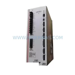
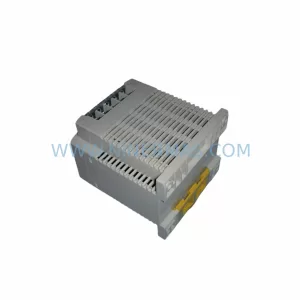
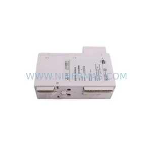
Original Industrial Spare Part
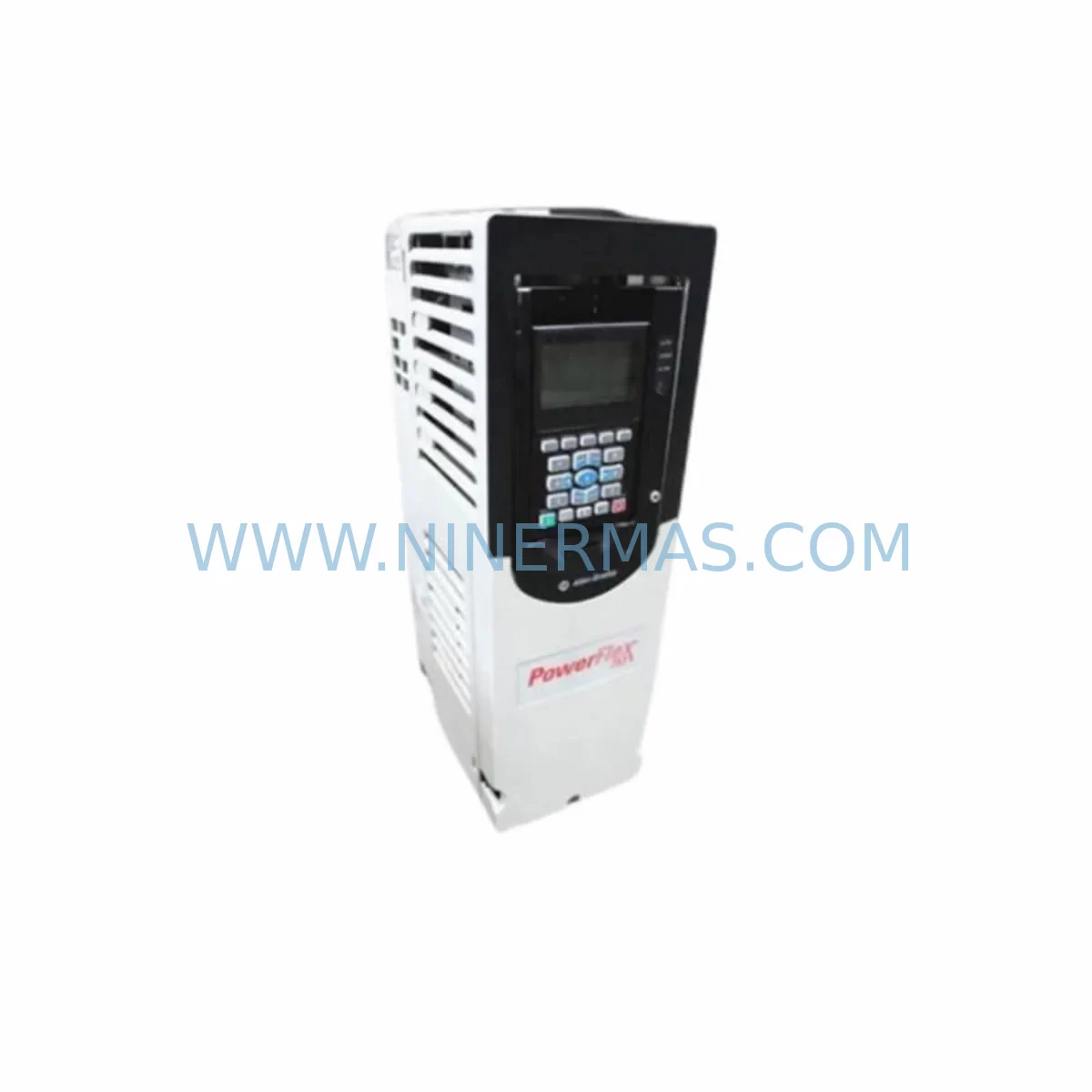
Allen-Bradley 20F11NC8P7JA0NNNNN Spare Part PowerFlex 755
Verify the part, confirm the platform family, and move straight into quotation with the right commercial details.
RFQ Ready
- SKU20F11NC8P7JA0NNNNN
- CategoryPLC & Industrial Automation Modules
- BrandAllen-Bradley
- SupportAvailability, lead time, condition, and shipping coordination
How Buyers Usually Use This Page
- Confirm the exact part number and platform family before sending the quote request.
- Use direct email when quantity, condition, and destination are already defined internally.
- Switch to the broader brand or category archive when you need alternates nearby.
Series Navigation
Move through the most common platform families behind this part.
Product RFQ
Send this part directly for quotation.
Include quantity, required condition, destination country, and target delivery timing. Current reference: Allen-Bradley 20F11NC8P7JA0NNNNN Spare Part PowerFlex 755 with SKU 20F11NC8P7JA0NNNNN.
Allen-Bradley 20F11NC8P7JA0NNNNN Spare Part PowerFlex 755: Rapid Replacement for Industrial Drive Downtime Control
The Allen-Bradley 20F11NC8P7JA0NNNNN is a service-ready spare part for the PowerFlex 755 AC drive series, engineered by Rockwell Automation for demanding industrial environments. This unit supports medium-voltage variable frequency drive applications across process manufacturing, discrete automation, and heavy-duty motor control systems. Maintaining a verified stock of the 20F11NC8P7JA0NNNNN is a critical element of any proactive maintenance strategy — particularly in facilities where unplanned drive failures translate directly into production losses, extended downtime, and costly emergency procurement cycles.
At NINERMAS, every 20F11NC8P7JA0NNNNN unit is pre-shipment tested, documented, and backed by a 12-month warranty. Our long-term supply program ensures consistent availability for both immediate replacement needs and planned annual maintenance schedules.
Spare Maintenance Table
| Parameter | Specification / Value |
|---|---|
| Part Number | 20F11NC8P7JA0NNNNN |
| Brand | Allen-Bradley (Rockwell Automation) |
| Series | PowerFlex 755 |
| Product Type | AC Variable Frequency Drive (VFD) — Frame 11 |
| Output Current Rating | 8.7 A (Normal Duty) |
| Input Voltage | 600 V AC, 3-Phase |
| Enclosure | IP20 / Open Type (suitable for panel or cabinet mounting) |
| Control Mode | Sensorless Vector, V/Hz, Closed Loop Vector |
| Communication | EtherNet/IP (integrated), DeviceNet, ControlNet compatible via option cards |
| Application Environment | Industrial process control, conveyor systems, pump/fan drives, compressor control |
| Ambient Temperature | 0°C to +50°C (operating); -40°C to +70°C (storage) |
| Compatibility | PowerFlex 755 drive family; Rockwell Automation Studio 5000 / RSLogix 5000 integration |
| Mounting | Panel mount; compatible with standard PowerFlex 755 frame 11 enclosure footprint |
| Condition | Original, pre-shipment tested, fully functional |
| Warranty | 12 Months — NINERMAS Quality Assurance |
| Lead Time | In stock; ships within 2–5 business days |
| Long-Term Supply | Available under NINERMAS spare parts commitment program |
Maintenance Planning for Continuous Operation
When a PowerFlex 755 drive unit such as the 20F11NC8P7JA0NNNNN is flagged during routine inspection or fails during operation, experienced maintenance engineers know that the drive itself is rarely the only component requiring attention. A thorough site assessment and cabinet inspection should accompany every drive replacement to prevent repeat failures and ensure system stability.
Begin by verifying the integrity of the input line reactor or EMC filter upstream of the drive — these components absorb voltage transients and harmonic disturbances that can degrade drive performance over time. Inspect the 24 VDC control power supply feeding the drive’s logic board and I/O interface; a marginal power supply is a common root cause of intermittent drive faults that are often misdiagnosed as drive failures. Check all terminal block connections on the drive’s input and output terminals for signs of thermal stress, oxidation, or loose torque — particularly on high-current conductors.
Review the status of the PowerFlex 755 option cards installed in the drive, including any EtherNet/IP communication adapter (20-750-ENETR) or encoder feedback module. These cards are field-replaceable and should be inspected for firmware compatibility when installing a replacement drive. If the system uses a Rockwell Automation 1756 ControlLogix or 1769 CompactLogix PLC as the motion controller, verify that the drive’s EDS file and IP address configuration are correctly restored after replacement to avoid communication faults on the network.
Inspect the motor cable insulation and verify that cable length does not exceed the drive’s rated output without a dV/dt output filter or sine wave filter in place — excessive cable capacitance can cause nuisance overcurrent trips on a newly installed drive. Check the motor thermistor (PTC) circuit wiring back to the drive’s analog input or dedicated thermistor input to ensure motor thermal protection is active.
For facilities running multiple PowerFlex 755 drives on a common DC bus configuration, inspect the common bus supply unit and precharge resistors as part of the replacement workflow. Additionally, review the dynamic braking resistor assembly if the application involves regenerative loads such as hoists, centrifuges, or winding machines — a failed braking resistor can cause DC bus overvoltage faults that damage a newly installed drive within hours of commissioning.
Annual maintenance schedules for PowerFlex 755 installations should include replacement of internal cooling fans (typically rated for 50,000 hours), inspection of DC bus capacitors for bulging or leakage, and a full parameter backup using Rockwell Automation Connected Components Workbench or Studio 5000. Keeping a parameter backup on file dramatically reduces commissioning time when a spare drive is installed during an emergency.
Site Replacement Workflow
Step 1 — Isolation and Safety: De-energize the drive following LOTO (Lockout/Tagout) procedures. Allow a minimum of 5 minutes for DC bus capacitors to discharge before opening the enclosure. Verify bus voltage with a calibrated meter before touching internal components.
Step 2 — Parameter Backup Verification: Confirm that a current parameter file for the failed drive is available. If not, attempt to retrieve parameters via the PowerFlex 755 HIM (Human Interface Module) or via network backup from the PLC program. Document all custom parameter settings, especially acceleration/deceleration ramps, current limits, and fault response configurations.
Step 3 — Physical Replacement: Remove the failed 20F11NC8P7JA0NNNNN unit following the PowerFlex 755 Frame 11 removal procedure. Install the replacement unit, ensuring all power and control wiring is reconnected to the correct terminals per the original wiring diagram. Torque all terminal connections to specification.
Step 4 — Option Card Transfer: Transfer any option cards (communication adapters, encoder modules, I/O expansion cards) from the failed unit to the replacement drive. Verify card seating and firmware version compatibility before energizing.
Step 5 — Parameter Restore and Commissioning: Restore the parameter file to the replacement drive. Perform a no-load test run to verify correct rotation direction, speed reference response, and fault-free operation before reconnecting the mechanical load. Confirm EtherNet/IP communication is re-established with the PLC and that the drive appears correctly in the network topology.
Step 6 — Documentation: Update the maintenance log with the replacement date, new unit serial number, and any parameter changes made during commissioning. Schedule the next preventive maintenance inspection per the site’s maintenance calendar.
Spare Parts Support FAQ
Q1: Is the 20F11NC8P7JA0NNNNN a direct drop-in replacement for an existing PowerFlex 755 Frame 11 installation?
Yes. The 20F11NC8P7JA0NNNNN is a standard PowerFlex 755 Frame 11 drive rated for 600 V, 3-phase input with 8.7 A output current. It is dimensionally and electrically compatible with existing Frame 11 enclosure footprints. Option cards from the original unit can be transferred directly. Always verify firmware version compatibility and restore the original parameter file during commissioning.
Q2: What pre-shipment testing does NINERMAS perform on the 20F11NC8P7JA0NNNNN before dispatch?
Every unit undergoes functional power-on testing, DC bus voltage verification, and output phase balance checks prior to shipment. Units are inspected for physical integrity, connector condition, and correct firmware version. A test report is available upon request. All units are shipped with ESD-protective packaging to prevent transit damage.
Q3: Can NINERMAS support long-term or blanket purchase orders for the 20F11NC8P7JA0NNNNN?
Yes. NINERMAS operates a spare parts commitment program designed for facilities requiring guaranteed stock availability over 12–36 month horizons. This program supports annual maintenance budgets, multi-site procurement, and emergency call-off orders with fixed lead times. Contact our sales team at sale@ninermas.com to discuss volume pricing and supply agreements.
Q4: What is covered under the 12-month warranty for the 20F11NC8P7JA0NNNNN?
The 12-month warranty covers manufacturing defects, functional failures under normal operating conditions, and any faults attributable to the unit itself. Warranty claims are supported by NINERMAS technical staff and include unit replacement or repair at no additional cost. The warranty period begins from the date of shipment. Damage resulting from incorrect installation, overvoltage events, or environmental conditions outside the rated specification is excluded.
| Product Series | PowerFlex |
|---|---|
| Country of Origin | US |
Catalog Continuation
More Allen-Bradley modules in the catalog.
Use the brand lane to compare nearby part numbers, platform-adjacent modules, and other inquiry-ready listings before sending your final RFQ.
Catalog Continuation
Alternative parts within PLC & Industrial Automation Modules.
Stay inside the same system family when you need substitutes, adjacent modules, or a broader shortlist for procurement review.
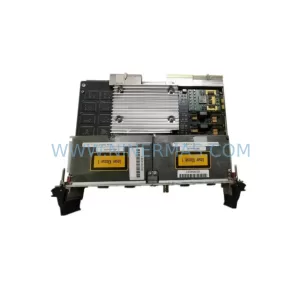
SKU: PCE-2 LIF-1 K15MB000 671-5532-02
Tektronix PCE-2 LIF-1 K15MB000 671-5532-02 Service-Ready Spare Part