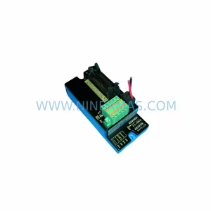
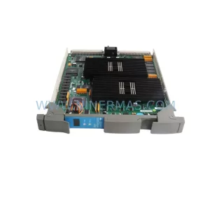
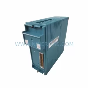
Original Industrial Spare Part
ABB AP1406TSM-2PW Retrofit-Compatible DCS Module for Legacy Systems
Verify the part, confirm the platform family, and move straight into quotation with the right commercial details.

RFQ Ready
- SKUAP1406TSM 2PW MV4 MVE4 P AP1402TS 2PW MVE4 MVE4 P 63039620193 7030_02
- CategoryDCS Distributed Control Systems
- BrandABB
- SupportAvailability, lead time, condition, and shipping coordination
How Buyers Usually Use This Page
- Confirm the exact part number and platform family before sending the quote request.
- Use direct email when quantity, condition, and destination are already defined internally.
- Switch to the broader brand or category archive when you need alternates nearby.
Series Navigation
Move through the most common platform families behind this part.
Product RFQ
Send this part directly for quotation.
Include quantity, required condition, destination country, and target delivery timing. Current reference: ABB AP1406TSM-2PW Retrofit-Compatible DCS Module for Legacy Systems with SKU AP1406TSM 2PW MV4 MVE4 P AP1402TS 2PW MVE4 MVE4 P 63039620193 7030_02.
ABB AP1406TSM-2PW Retrofit-Compatible DCS Module for Legacy Systems
The ABB AP1406TSM-2PW MV4 MVE4 P is a process controller module originally designed for the ABB Bailey INFI 90 Distributed Control System platform — one of the most widely deployed DCS architectures in power generation, chemical processing, pulp and paper, and refining industries. As ABB has progressively discontinued the AP1400 series, maintenance engineers and system integrators face increasing pressure to source verified replacement units that can be installed without triggering a full control system overhaul. This listing covers the AP1406TSM-2PW MV4 MVE4 P as a retrofit-compatible replacement, pre-tested and supplied with a 12-month warranty to support your legacy system continuity strategy.
The companion module AP1402TS-2PW MVE4 MVE4 P (part number 63039620193, revision 7030/02) is closely related in architecture and is frequently replaced alongside the AP1406TSM-2PW during control cabinet upgrades. Both modules share the same INFI 90 backplane interface and are subject to the same end-of-life supply constraints, making it critical to source both from a supplier with verified inventory and documented test records.
Upgrade Compatibility Table
| Parameter | AP1406TSM-2PW MV4 MVE4 P | AP1402TS-2PW MVE4 MVE4 P |
|---|---|---|
| Series | ABB Bailey INFI 90 / AP1400 | ABB Bailey INFI 90 / AP1400 |
| Backplane Interface | INFI 90 Module Bus | INFI 90 Module Bus |
| Power Supply Requirement | 24 VDC (2PW configuration) | 24 VDC (2PW configuration) |
| I/O Configuration | MV4 / MVE4 analog I/O | MVE4 / MVE4 analog I/O |
| Communication Protocol | INFI-NET / Module Bus | INFI-NET / Module Bus |
| Mounting | INFI 90 standard rack | INFI 90 standard rack |
| Replacement Recommendation | Direct drop-in for AP1406TSM variants | Direct drop-in for AP1402TS variants |
| Commissioning Note | Verify module address and loop configuration before power-on | Verify terminal wiring and analog scaling |
| Pre-Shipment Test | Yes — functional test performed | Yes — functional test performed |
| Warranty | 12 Months | 12 Months |
Retrofit Planning for Existing Automation Systems
Replacing an AP1406TSM-2PW in a live INFI 90 system requires careful pre-work to avoid unplanned shutdowns and configuration loss. Before removing the existing module, engineers should document the current module address settings using the INFI 90 engineering workstation and export the loop configuration from the Process Control Unit (PCU). The PCU — often an IMPCX01 or IMPCX11 — holds the control strategy that references each module slot by address; any mismatch after replacement will cause the PCU to flag a hardware fault and suspend the affected control loops.
Terminal wiring on the AP1406TSM-2PW follows the standard INFI 90 field termination unit (FTU) scheme. If the existing FTU is an NTMP01 or NKMP01 type, the wiring can typically be transferred directly to the replacement module without re-termination, significantly reducing installation time. However, if the cabinet uses an older IEPAS02 power entry assembly, the 24 VDC supply rail should be verified for adequate current capacity before inserting the new module — particularly if other modules such as the IMASI03 analog input or IMDSI02 digital input modules are drawing from the same rail.
For sites running INFI-NET communications, the replacement AP1406TSM-2PW must be configured with the same node address as the failed unit. This is typically set via DIP switches on the module face. Cross-reference the original engineering drawings or the INFI 90 system database before setting the address. If the site also uses an IMFEC12 fieldbus interface or an INNIS21 network interface module for higher-level SCADA integration, confirm that the communication link remains intact after the module swap — a brief INFI-NET interruption during hot-swap can cause the SCADA historian to log a gap in process data.
HMI screens connected via an IMMPI01 multi-port interface or a legacy OIS (Operator Interface Station) should be monitored during commissioning. After the replacement module is seated and powered, the HMI should automatically re-establish the tag references within one to two scan cycles. If tags remain in error state, a soft reset of the PCU loop may be required — this can be performed from the engineering workstation without interrupting other control loops in the same rack.
For I/O expansion scenarios where the AP1406TSM-2PW is being replaced as part of a broader upgrade — for example, adding additional analog output channels — consider whether the existing INFI 90 rack has available slots. If the rack is fully populated, a secondary rack with its own IMCIS02 communication interface module may be required to extend the I/O count without disturbing the existing module layout.
Downtime Control During System Migration
Minimizing downtime during an AP1406TSM-2PW replacement begins with preparation, not execution. The most effective approach is to pre-configure the replacement module offline using a spare INFI 90 rack or a bench test setup, verify its functional response with a signal simulator, and only then schedule the field swap during a planned maintenance window.
Where process conditions allow, consider placing the affected control loops in manual mode at the DCS operator station before pulling the module. This preserves the last output value on the field actuators and prevents a bump to the process when the module is removed. Once the replacement is seated and the module bus handshake is confirmed, the loops can be returned to automatic mode one at a time, with the operator monitoring the process variable trend for any unexpected deviation.
For critical loops — such as those controlling furnace temperature, reactor pressure, or compressor surge — it is advisable to have a second engineer at the field instrument during the switchover, ready to intervene manually if the control response is not as expected. Document the pre-swap and post-swap process values as part of the change record, and retain the removed module for at least 30 days in case a rollback is required.
Our pre-shipment testing protocol covers power-on verification, module bus communication check, analog I/O channel calibration, and a 48-hour burn-in cycle. Each unit ships with a test report. Combined with the 12-month warranty, this gives maintenance teams a documented baseline for the replacement unit’s condition at the time of installation.
Retrofit Support FAQ
Q1: Is the AP1406TSM-2PW MV4 MVE4 P a direct replacement for the AP1402TS-2PW MVE4 MVE4 P?
A: The two modules share the same INFI 90 backplane interface and 24 VDC power configuration, but they differ in I/O channel count and internal firmware. In most retrofit scenarios they are replaced independently. Confirm the module address and loop assignments from your engineering drawings before substituting one for the other. Contact our technical team with your PCU configuration file if you need a compatibility assessment.
Q2: What pre-shipment testing is performed on each unit?
A: Every AP1406TSM-2PW unit undergoes power-on verification, module bus communication handshake, analog I/O channel functional test, and a 48-hour burn-in cycle. A test report is included with each shipment. Units that do not pass all test stages are not shipped.
Q3: How do I confirm terminal wiring compatibility with my existing field termination unit?
A: Identify the FTU model installed in your cabinet (typically an NTMP01, NKMP01, or equivalent). Cross-reference the terminal assignment drawing for your specific AP1406TSM-2PW variant against the FTU wiring diagram. If the FTU was originally wired for the same module variant, no re-termination is required. We can provide wiring guidance based on your module revision and FTU model upon request.
Q4: What is the warranty coverage and what does it include?
A: All units are supplied with a 12-month warranty from the date of shipment. The warranty covers functional failure under normal operating conditions and includes return-and-replace service. It does not cover damage resulting from incorrect installation, overvoltage, or environmental conditions outside the module’s rated specification. Warranty claims are processed within 5 business days of receipt of the returned unit.
| Product Series | Infi 90 |
|---|---|
| Country of Origin | SE |
Catalog Continuation
More ABB modules in the catalog.
Use the brand lane to compare nearby part numbers, platform-adjacent modules, and other inquiry-ready listings before sending your final RFQ.
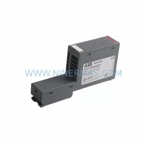
SKU: TA524 1SAP180600R0001E
ABB 1SAP180600R0001E Safety-Reliable Terminal Coupling Module
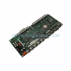
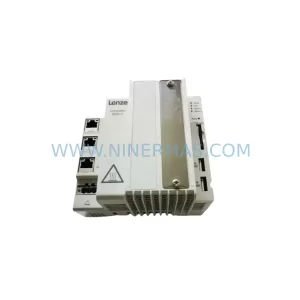
SKU: 32GAC00000P5H0XXX-02S13340000
ABB 32GAC00000P5H0XXX-02S13340000 Retrofit Controller Module
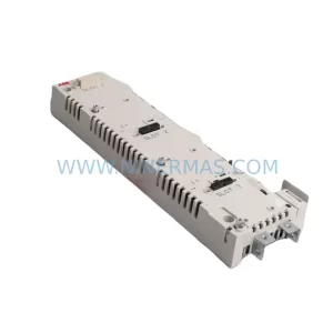
SKU: JCU-01 68592917N
ABB JCU-01 68592917N Service-Ready Spare Part for Industrial Maintenance
Catalog Continuation
Alternative parts within DCS Distributed Control Systems.
Stay inside the same system family when you need substitutes, adjacent modules, or a broader shortlist for procurement review.